Wiki:
An actuator is a component of a machine that is responsible for moving and controlling a mechanism or system, for example by opening a valve. In simple terms, it is a “mover”.
Digital output: LED’s
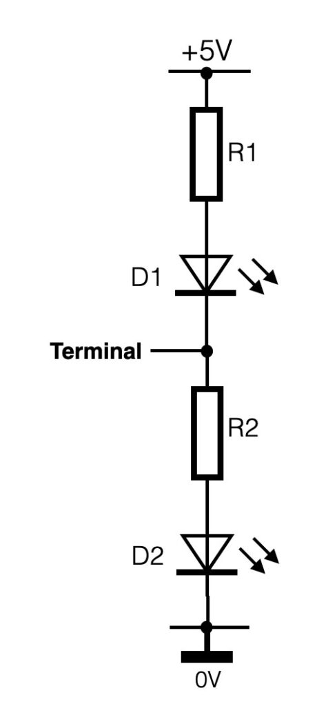
LED’s can be driven by terminals in either digital or analog output modes. Digital output provides on/off, whereas analogue output provides a signal that looks like dimming the intensity of the light – we call this PWM, or Pulse Width Modulation.
For digital output connected like the figure on the right, D1 will light up when the terminal is 0V (Low) and D2 will light up when the terminal output is high (+5V).
If you want to change the intensity of the light, or the speed of a motor we use Pulse Width Modulation. An Arduino or any other interface is a digital device. And a digital device only knows two states: On/Off, Yes/No, One/Zero. So if analogue output is mentioned, this is not really “true”.
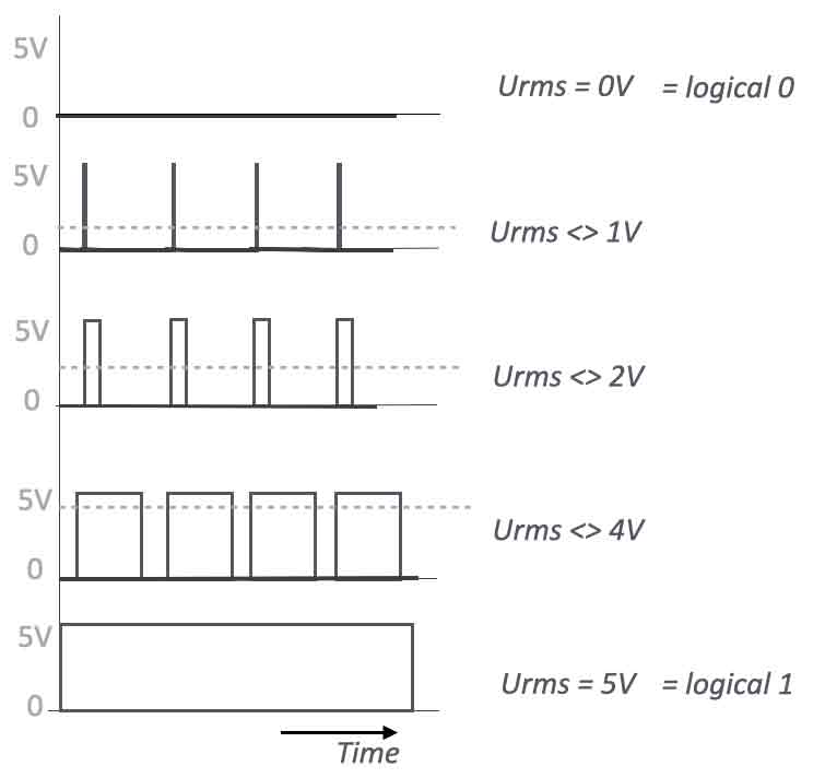
PWM outputs
PWM is a method of changing the width of the pulse, so the average signal value will increase or decrease. In the Arduino language an ‘AnalogWrite(variable, xxx); creates a pulse width modulation signal.
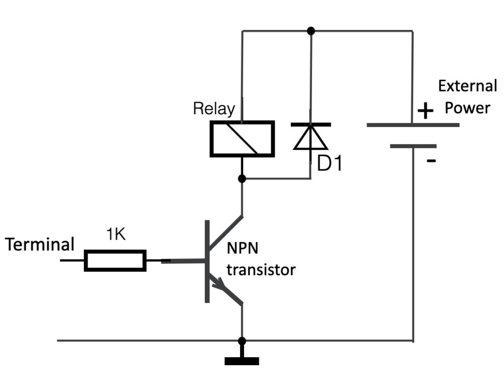
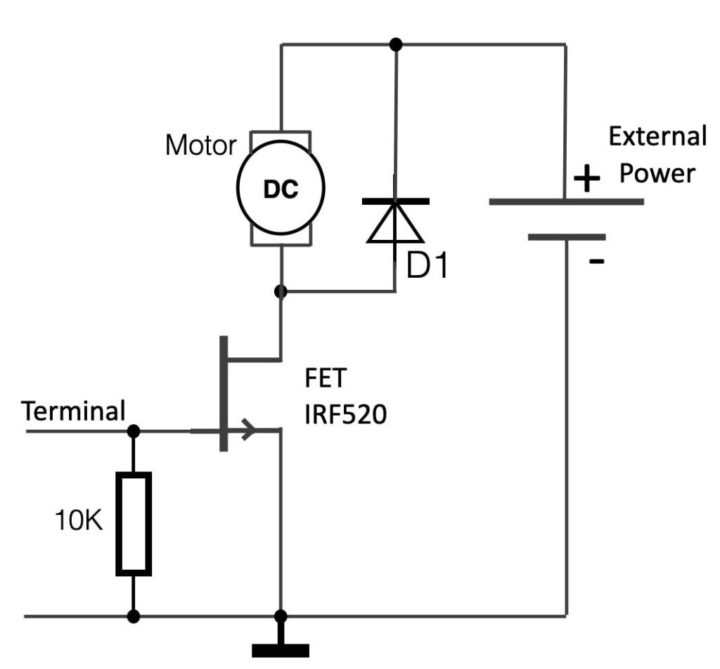
The Arduino or any other microcontroller device is not capable of providing a lot of current – in other words, if you want to connect an (heavy) actuator that really needs lots of current to ‘move’, you have to interface it. In between the output of the microcontroller and the actuator extra electronics is needed to ‘amplify’ the current.
Below a few circuit examples.