What is Arduino?
Arduino is an open-source electronics platform based on easy-to-use hardware and software. It’s intended for anyone making interactive projects.
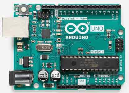
An Arduino board as shown above (UNO revision3) is in fact a small sized computer that can be easily programmed by the user to do all kind of conversions. When we compare the Arduino with a real computer, it does not have the general input and output devices like the screen, keyboard or mouse. Instead it only has analog/digital voltage-inputs and voltage-outputs. For more extensive information about Arduino, visit their website: https://www.arduino.cc/
Inputs and Outputs
The standard Arduino Uno has 6 analog inputs (A0 – A5). These inputs are connected to a 10-bits Analog-Digital Convertor (ADC). The voltage changes between 0V and 5V can be applied to these 6 pins, are converted into a number that has a resolution of 10 bits ( 210 = 1024 steps).
Besides the special analog inputs, the Arduino Uno has 12 digital In/Outputs, from which 6 are defined to be PWM. The other half is only digital On/Off. In the software program (the patch) the user can define which pin of the Arduino will be input or output.
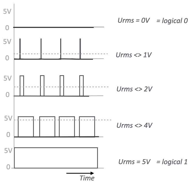
An Arduino is a digital device. This means it only deals with ‘0’ and ‘1’. An output that is called analog in this case is in fact a digital output, but with a very fast switching mechanism called Pulse Width Modulation. All the outputs that are marked with a ~ are ‘analog’ outputs, that will generate PWM.
Getting started
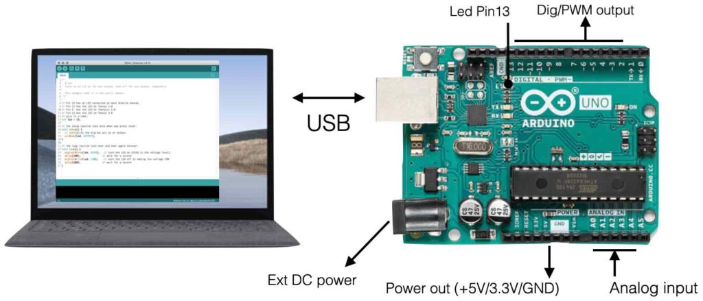
The first step in programming your own Arduino is to connect the Arduino-board to your computer using the right USB-cable. Your computer will recognize the board and no external drivers have to be installed. You will notice the small led (pin13) lighting up, indicating the board has power.
The next step is to download the Arduino software, which enables you to write your program and program the board. Check this link: https://www.arduino.cc/en/software to download the latest IDE. The open-source Arduino Software (IDE) makes it easy to write code and upload it to your board.
Simple Example – equipment test
The best way to test your Arduino/Computer setup, is to start with a simple example like the program ‘blink’. This program makes the onboard led ( = pin 13) light-up (ON) and Off with a time delay of 1 second.
Basically this program is not of any ‘practical’ use other then check the setup and getting to know the way the Arduino works. On the other hand, you create a rectangle wave-shape with a frequency of 0,5Hz on the output of the board = pin 13 (delay time ON=1000mS and delay time OFF is 1000mS). The blink-program also shows you the fundamental setup or configuration of a program or ‘patch’.
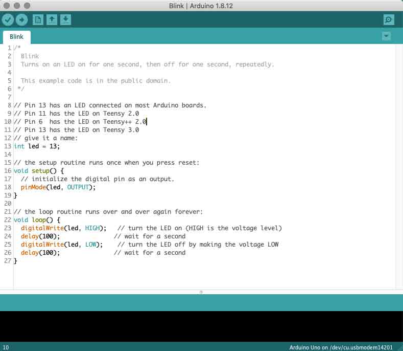
The code in the picture above show the most fundamental setup of a program or patch. The tekst that is ‘grayed out’ or starts with //, is comment and not part of the code, other than documentation for you.
There are 3 parts in the code:
- First you have the initialization, or definition of all the variables and pin(numbers) within the code. In the example above only the Integer variable “led” is defined.
- Second is the void setup(). In this part of the code you can configure the Arduino. pinMode(Led, OUTPUT) is sets pin 13 to be an output. This piece of code will only run once during start. After that it only reloads when a hard reset is given.
- The last part is the main loop of the code: void loop() All the code within this loop will run until shutdown.
In the Blink example there are 4 instructions that are looped:
DigitalWrite(Led, HIGH) – this sets pin 13 (= variable Led) to HIGH (= +5V)
Delay (100) – wait for 100 mili seconds
DigitalWrite(Led, LOW) – this sets pin 13 (= variable Led) to LOW (= 0V)
Delay (100) – wait for 100 mili seconds
After the last delay it loops until shutdown. The LED will blink:-). If you start with this blink example you can check, without connecting any extra electronics, the basic communication between your board and computer.
Basic Sensor reads and Serial Write
Since most of the users want to ‘measure’ something and then ‘do’ something based upon the outcome of the measurement, the next example is a good insight in how to make this work.
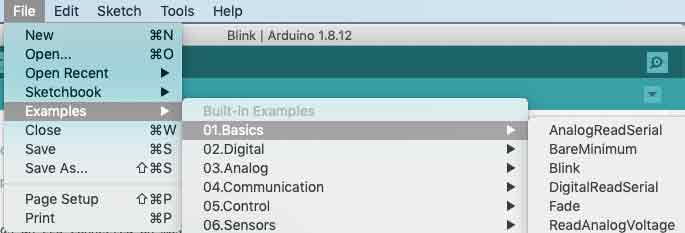
Open: Files/Examples/Analog/AnalogInOutSerial
This code reads the voltage on pin A0 ( analog input 0) and converts this data to PWM on output pin 9~. At the same time it will send data to its serial ports (Tx and Rx) so other software within your computer can work with it (SuperCollider, Max/Msp, PureData, Processing, … )
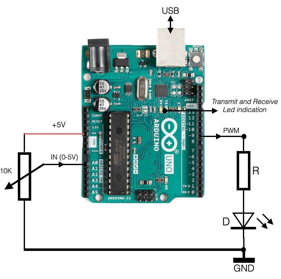
In the setup above we have a potentiometer connected between the +5V dc and the GND (0V). When we turn the knob of the pot we can make a voltage change between 0V and 5V as a continues signal. The wiper of the pot is connected to analog input A0, so the ADC will generate numbers between 0 and 1024 ( = 10 bit resolution or 210)
Pin 9~ is the Pulse Width Modulation output. It is connected to a led through a resistor (limit the current!). When the output PWM signal is 100% (AnalogWrite = 255) the led will light up with maximum intensity. The lower the output value, the less light the led will produce.
Let’s take a closer look at the code.
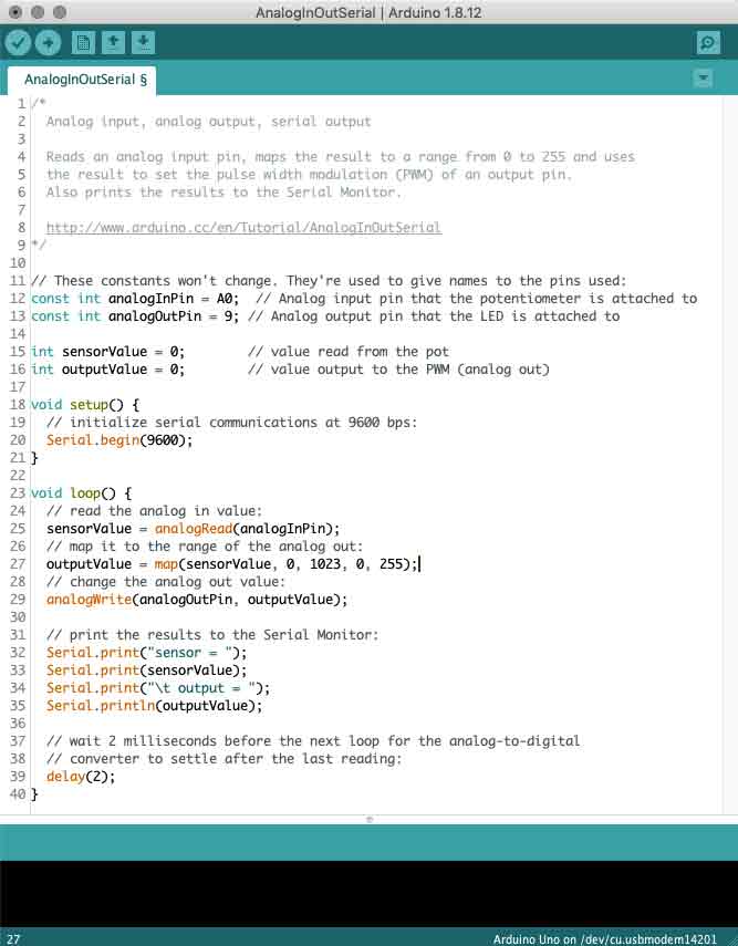
This AnalogInOutSerial code is also divided in three parts. First we have the definition of the variables used in the code: analogInPin, analogOutPin, SensorValue, outputValue. All these variables are defined defined to the type Integer (only whole numbers).
The next part is the void setup() where the speed of the serial port is set. This speed has to be the same within the software the Arduino is communicating with. If you for example want to read this data into PureData (Pd), then the communication port of Pd has to be set to the same speed – otherwise both devices do not understand each-other.
Then the loop part, called void loop()
First of all the value of the sensor is read on input A0. This is a value between 0 and 1024 (10bits). After that the variable ‘outputValue’ will be given the value of the sensor (sensorValue), but then remapped or divided by 4. This is because the output resolution is 8bit (0-255).
The analogWrite instruction generated PWM on the output pin number 9. The value measured at the input has now been transferred to the PWM output.
In the last part of the loop, the values are ‘printed’ to the output with the instruction Serial.print(value). The Serial.print() instruction sends the value (tekst or data) through the USB port (Tx) to your computer. More about this subject, click here. To make sure the processor does not go too fast, a delay of 2ms is embedded.