Electronics … Let’s start
Electronics is an absolute fascinating world with the possibility to create any circuit and any functionality that you would like. But bear in mind: electronics can be very complex and frustrating as well. Circuits that do not work. Components that smell funny or circuits which are unstable. How do you cope with that? Let’s start with the fundamentals of electronics:
Wiki definition: Electronics deals with electrical circuits that involve active electrical components such as transistors, diodes and integrated circuits, and associated passive interconnection technologies. The nonlinear behavior of active components and their ability to control electron flows makes amplification of weak signals possible and electronics is widely used in information processing, telecommunications, and signal processing
Electronics is about the control of current in a circuit. If the current somewhere in the circuit is too small, it is not stable or not reliable. If the current too high, the temperature will be too high. It has to be somewhere in the middle. These lessons will give you a complete introduction to Electronics. We will focus on the basics and fundamental circuits that are applied in music and art. We will talk about the common applied components, passive and active and also the small programmable computers (Arduino, Teensy), or sensor interfaces will be part of the subjects.
Electrical current
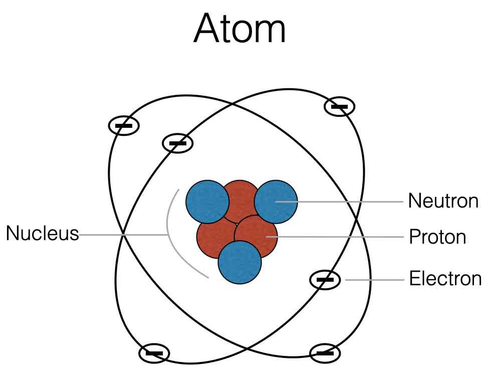
All materials you can imagine are made out of atoms. The core of an atom is the nucleus which has protons and neutrons. In the outer shells there are electrons. Check the picture below.
Materials that do not conduct current, like wood, glas or plastic do not have free electrons, because the nucleus with positive particles is in balance with the negative electrons. Materials like copper, gold or metal are not in balance. They have more electrons in the outer shells which are not linked to the positive nucleus – this means they are free to move through the material. We have free electrons and thus: conductance.
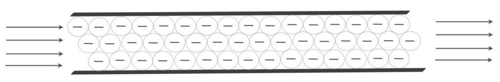
When you think about current through a wire, you can imagine electrons like marbles (or water), that are pushed through a pipe (see image above). Electrical current is measured in Amperes. If the current is one ampere (1A), it means that in one second 6,242*1018 electrons pass a given point. The more current flows through a wire, the thicker the wire should be. Check the video section of the webiste.
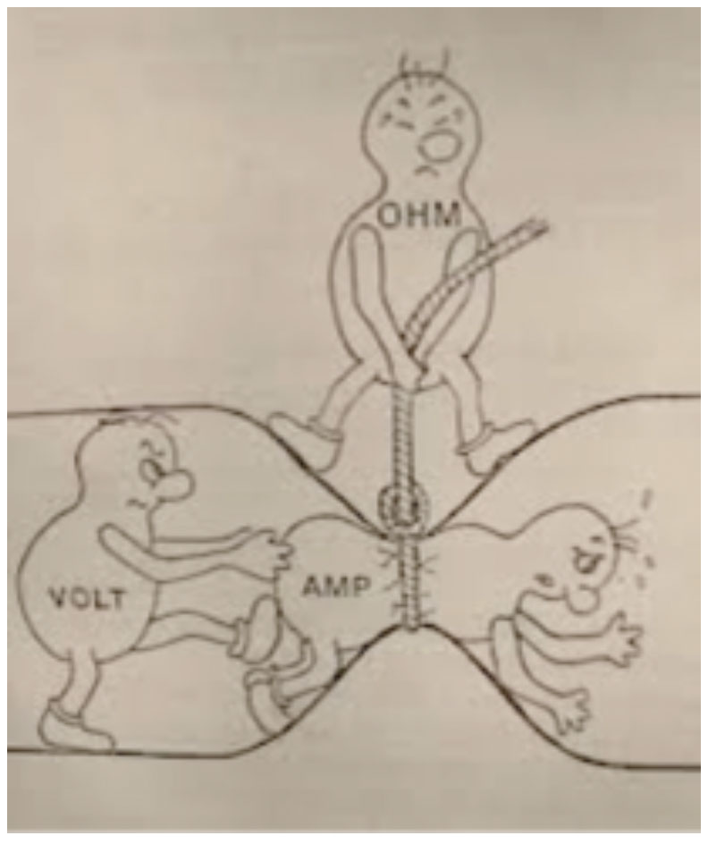
The amount of current (Ampere) through a wire is determined by the applied Voltage (V) to that wire and the amount of resistance (Ohm) of that wire. This brings us to Ohms law.
Ohms law
Some basics of electronics
To be able to understand a bit more about electronics and the circuits that are shown on this or other websites, it is actually inevitable to understand Ohm’s law – it makes live a bit easier. You have to understand what happens with the current, the voltage and the resistance. All these three variables are linked and make part of ‘Ohms Law’.
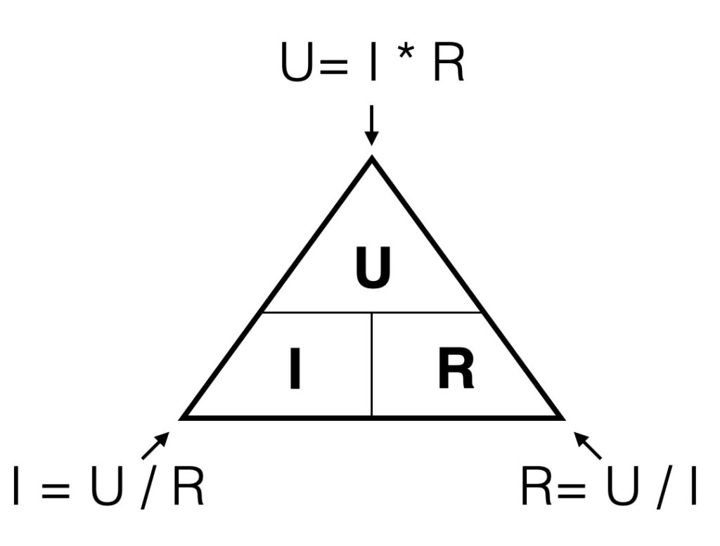
In formula: U = I x R
The voltage [V] is a product of the current {A] times the resistance [Ohm])
A graphical representation of this formula: when you look to the triangle from one of the three angles, you ‘see’ the formula’s for every variable. If you look from the top you ‘see’ U = I*R. Looking from the left corner beneath, you ‘see’ I=U/R.
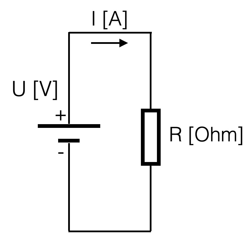
In other words: the higher the value of the resistor, the lower the current given a constant voltage (the battery). If the resistance is 0 Ohm, we call this a short-circuit. A short circuit will result in a undefined value (too high) of the current (dividing by zero is not possible)
Suppose you have a battery of 9V. If you connect a resistor of 1kOhm (=1000 Ohm) parallel, the resulting current will be:
I = (U / R) = 9 / 1000 =
9 mA = 0,009 Ampere (A) (9 mili Amp)
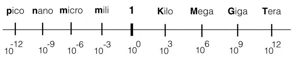
Within electronics, the values we use will vary from Tera (= 1000000000000) or 1012 ( a one with 12 zero’s) to pico: 0,000000000001. The engineering values always take steps of ‘3’ digits, in order to keep the notation clean and avoid errors.
Series
Voltage divider
If resistors are placed in series (see figure below), the total resistance is a summation of al the resistors. So the total resistance in the example below is: R1+R2. If more resistors are placed in series, just add them up. If you have the total resistance, the current can be calculated in that circuit with ohm’s law.
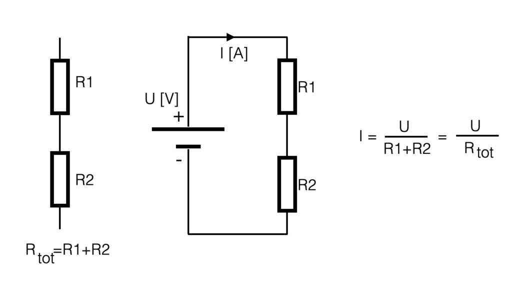
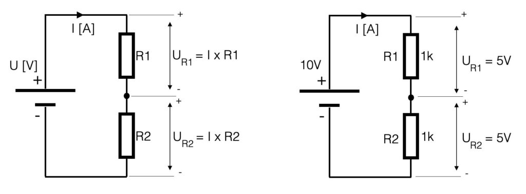
The current (I) in the series-circuit (see above) is the same in the whole circuit. There is only one branch. The voltage however is divided into equivalent parts. Another name for the circuit above is a voltage divider. The current through a resistor causes a ‘voltage-drop’ so with two resistors the voltage is divided into two values. If the series resistors have the same value (let’s say 1k), the value of the voltage parallel to the resistors is the same – the voltage is divided in equal parts. In case of the example below, the 10V of the power-supply is divided into two times 5V.
Be aware of the values that you use with these kind of calculations. Try to make use of the ‘engineering-values’ and avoid shifting comma’s. See the figure below.
If we would look at the series circuit defining an input and an output, the battery is the input and the voltage parallel to R2 is defined to be the output. This is an important definition when we start to talk about filters!
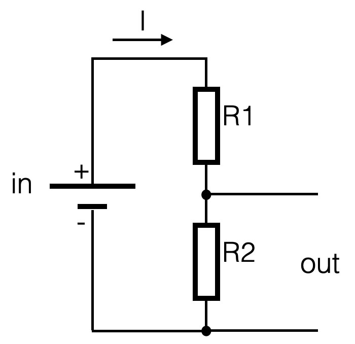
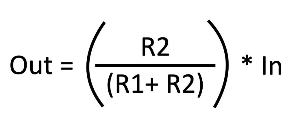
The output of this series-circuit can be defined like this:
Parallel
Current divider
If resistors are placed parallel (see figure below), they divide the current in equivalent parts – hence the name current divider. The voltage parallel to the two resistors is for both resistors the same – it is one electrical node (= electrical point). The current however is divided into two separate current flows. The amount of current is determined by the value of the resistor. See the figure.
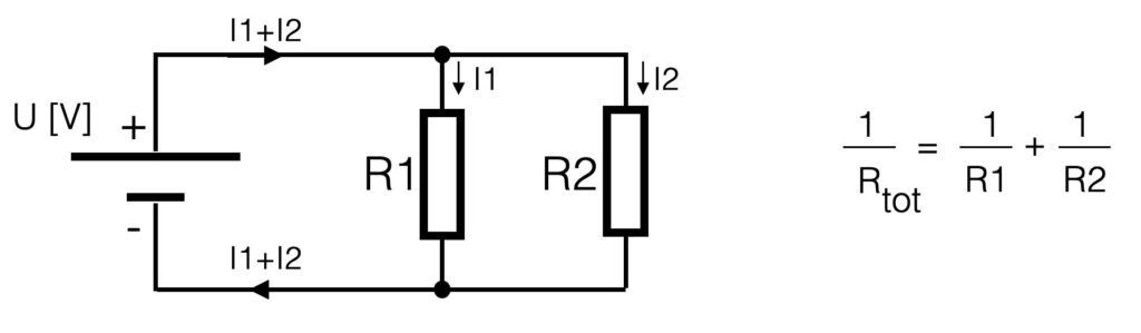
The total resistance of parallel resistors is the inverse of the series switched resistors. To calculate the total resistance you have to sum the inverses. This means that when resistors are connected parallel, the total resistance will go down. Suppose we have 2 resistors of 1kOhm placed parallel, the total resistance will be 500 Ohm.
Kirchoff
The behavior of current and voltage in a circuit is defined by the two laws of Kirchoff:
Kirchoff’s first law:
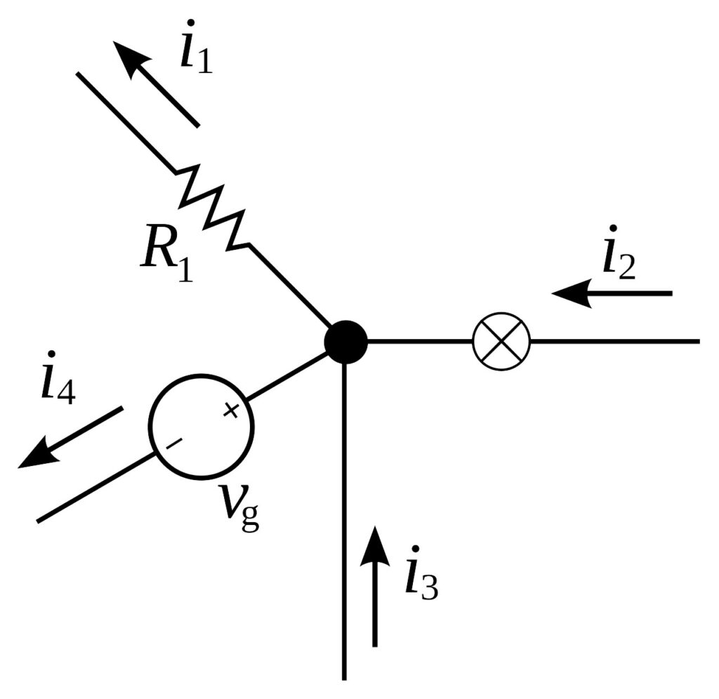
For any node (junction) in an electrical circuit, the sum of currents flowing into that node is equal to the sum of currents flowing out of that node.
This means that the current entering any junction is equal to the current leaving that junction. In math: i2 + i3 = i1 + i4
Kirchoffs’s second law:
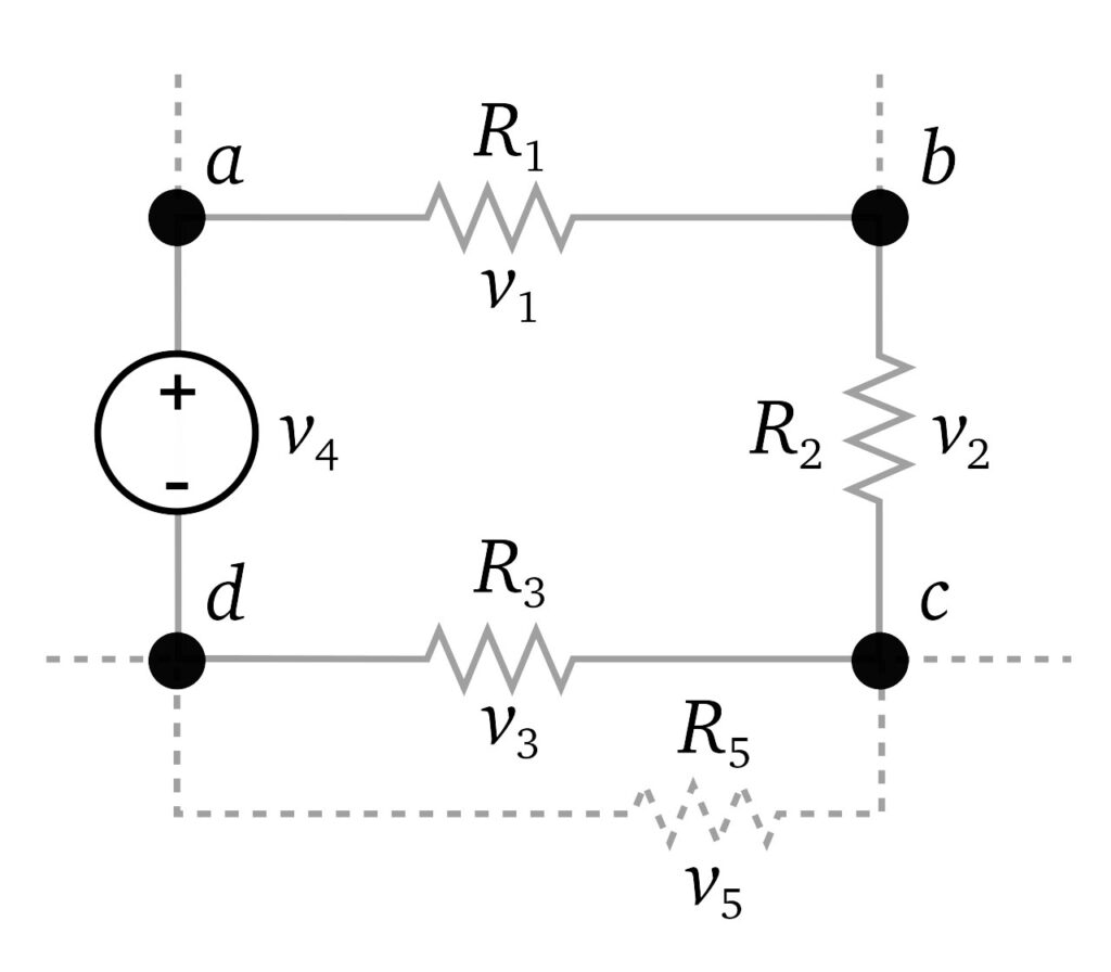
The directed sum of the potential differences (voltages) around any closed loop is zero.
The sum of all the voltages around a loop is equal to zero. In other words:
v1 + v2 + v3 +v4 = 0
AC and DC
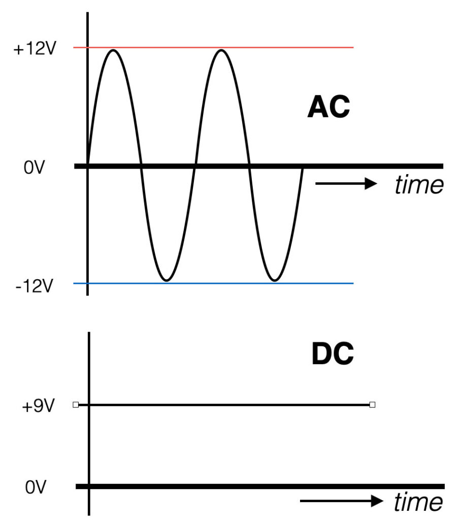
AC stands for Alternating Current. The value of the signal changes polarity over time with a certain frequency. The AC current will move both ways – back and forth.
DC stands for Direct Current. This means that the voltage does not change polarity over time. It is a straight line in the figure. Think about a battery. The plus (+) and minus (-) indicate you are dealing with DC. The current in the wire will move in one direction only.
Frequency
The frequency of a signal defines the amount of changes per second and is measured in units of Hertz [Hz]. So if we have an AC signal that changes (polarity) over time, this signal has a certain frequency.
Looking at the figure below you see a representation of a sine-wave. The circle on the left represents a rotating point (think of the pedal of a bicycle) – with starting at point “A”. The point rotates left and will go up towards point “B”. If we would draw the position of the moving point in time, we will see the first 90 degrees of a sine-wave. Following the pedal from “C” to “D” and back to the beginning at point “A”, we see a full sine-wave (360 degrees). This one full circle is also called one cycle (T). The variable T indicates the cycle time in seconds.
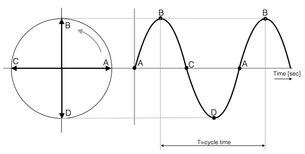
The amount of cycles that fit into one second (1 sec) is called the frequency F. So if we talk about a frequency of 1kHz (=1000Hz) this means that this signal makes 1000 cycles in one second.
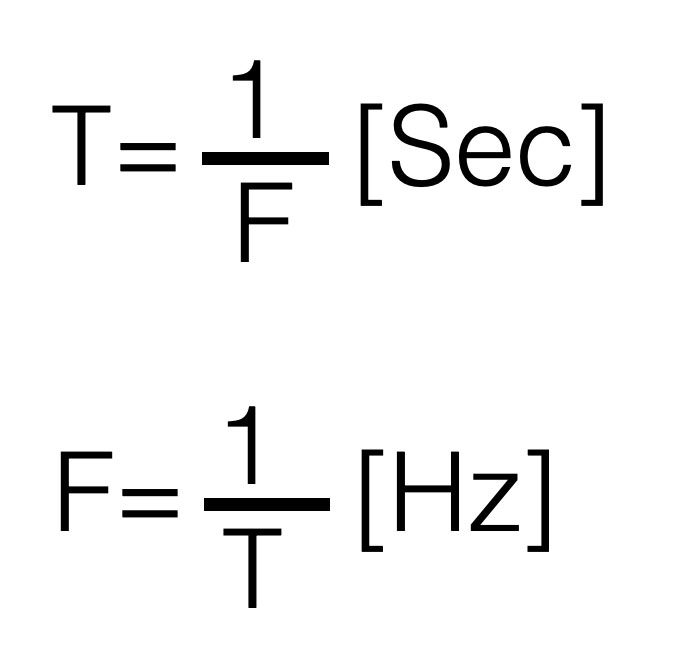
Written in formula this looks like this. The smaller the cycle time , the higher the frequency.
Amplitude
The Amplitude, often indicated with “A” is a value for the “strength” of a signal. The Peak to Peak Amplitude (A2 in the figure) is the change between the two ‘peaks’ of the sine-wave – the maximum swing.
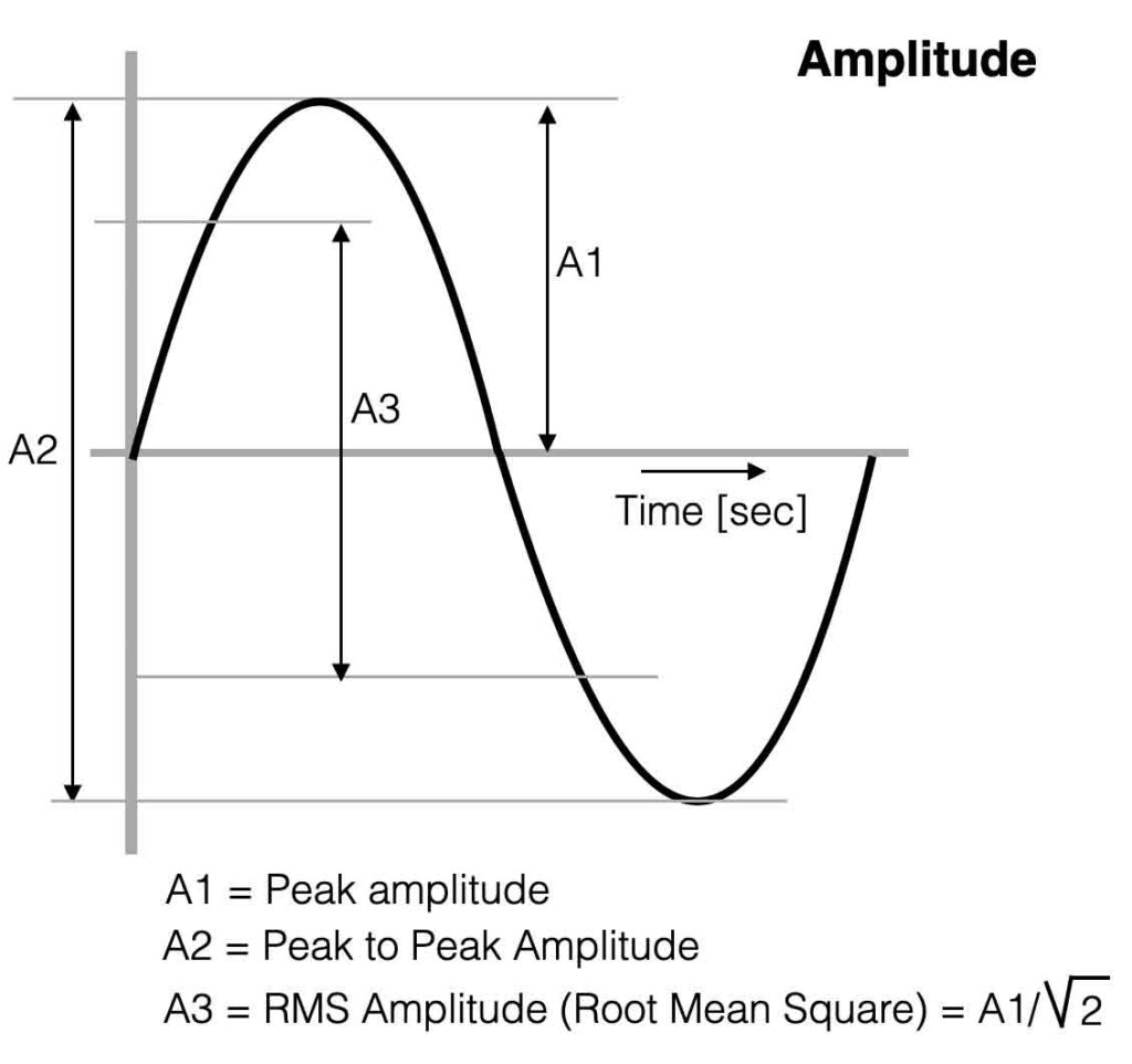
If you want to measure the average value of the sine-wave, this is called the RMS value of the Amplitude. (A3) The multimeter shows the RMS-value.
Phase
A mono signal cannot have ‘phase’, because phase is referring to a time difference between two repetitive signals. A sine-wave and a cosine-wave for example have a phase ‘angle’ of 90 degrees ( = 1/2π).
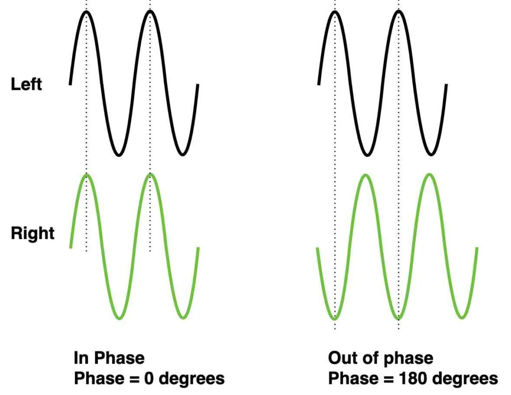
When two speakers are connected to an amplifier the correct way, both loudspeakers move forward and backward exactly the same time – the waves are ‘in phase’. If the connection of one speaker is then inverted (minus and plus swapped) we introduce two speakers that are ‘out of phase’. Check the waves below.
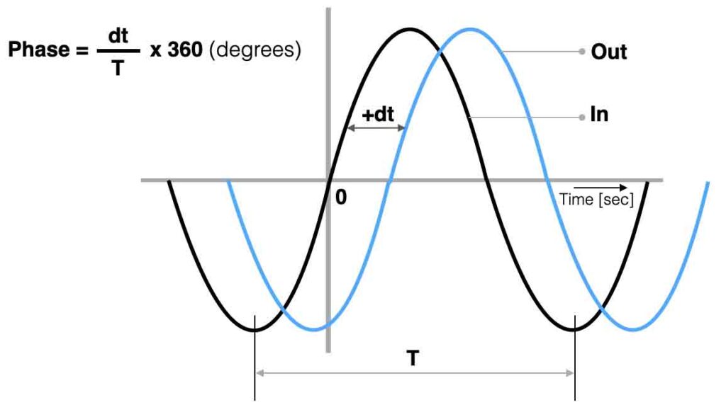
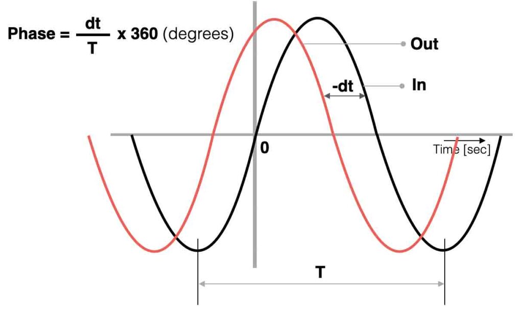
Electronic filters are created with time dependent components like capacitors or coils. When we connect an ac-signal (audio signal) to the input of a filter we can compare the in- and output to determine the ‘phase angle’ between both signals. In the figures below a positive- and negative phase example.