Building Electronics ‘tips’
When you want to make your own electronic device for the first time ever, you will encounter some challenges. How do you start? How can you make electronics stable and reliable. On this page some fundamental tips to help you create your own device.
Tip:
Try to build the board or circuit ‘modular’. Do not build all parts of the circuit at once and on the end of the line connect the power, finding out it does not work. This can be very frustrating. Test your circuit while you are building. Build small sub-parts of the total circuit and test them separately.
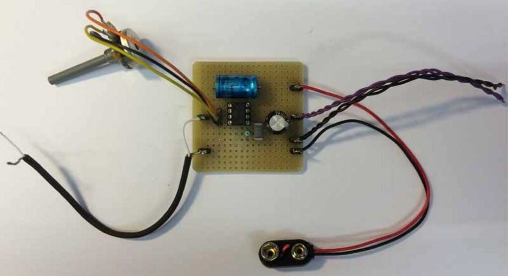
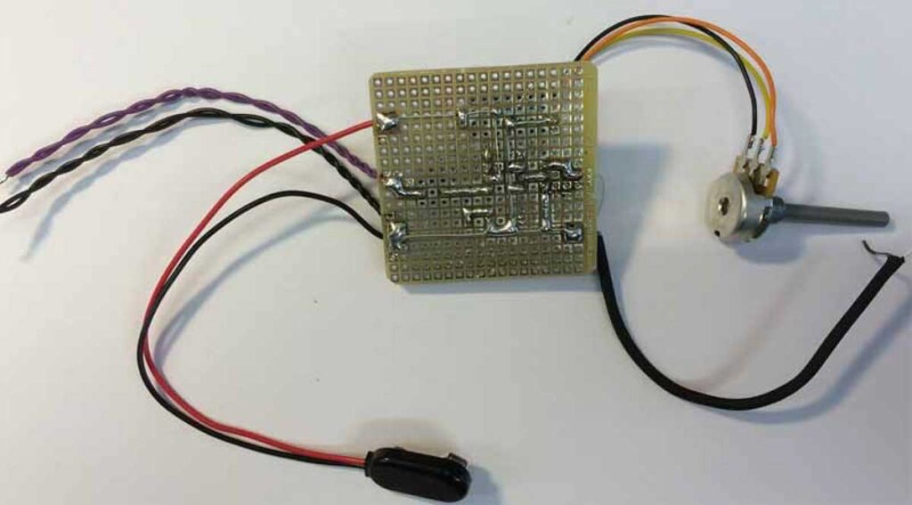
Connect (or route) the power supply of the circuit first. Add functionality later. Try to use wire color consequently, especially for power connections: Red for plus power supply, black for ground, and blue for negative power supply. This way it is easier to check for mistakes. If you do not have these colors available, try to stick labels to the wires.
Use the right cable for the right purpose: Thick(er) cable when the current is expected to be high (think of big speakers). Use shielded cable when the signal is very weak and/or high frequent. When you think the wire will move around (or vibrate), choose a cable that is flexible so it wont’ break.
Always build safe. Officially, by rule, any voltage above 48V is considered dangerous. When you are working with 230V~ AC, make sure no finger can touch /reach these voltages. Use good isolation and always be ‘aware’ of this lethal potential energy.
When touching 230V~AC, it’s the frequency in combination with the high voltage that’s dangerous. Our heartbeat is about 60 times per minute; one time per second. The frequency of the net is 50Hz; 50 times per second …
Building a Printed Circuit Board
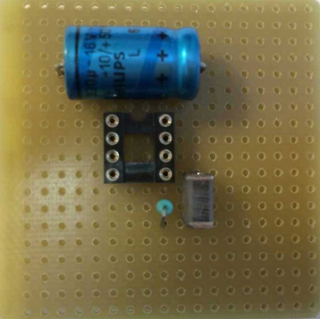
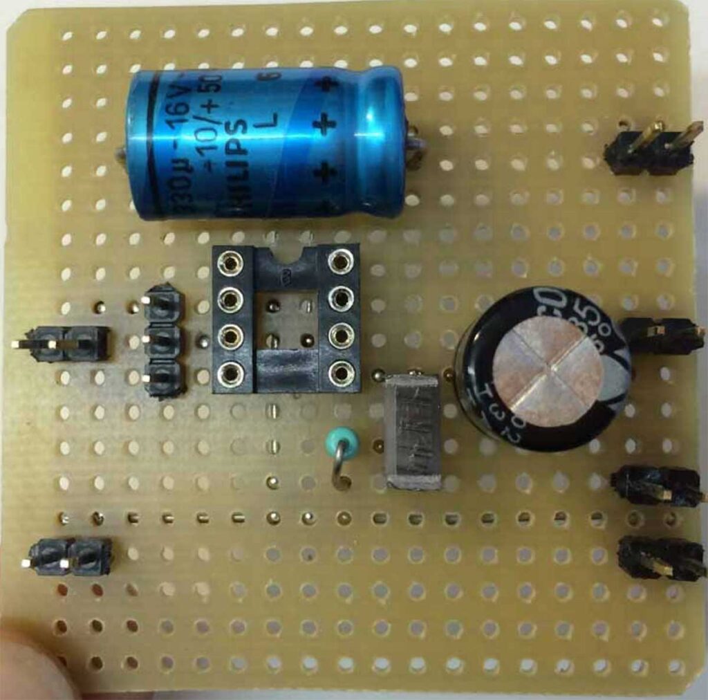
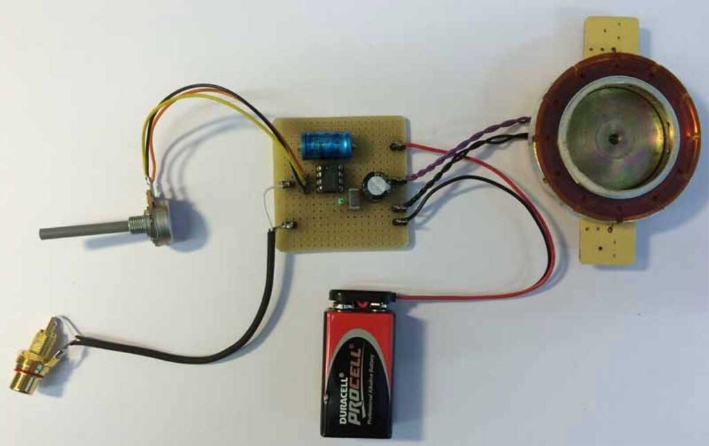
Proto typing example
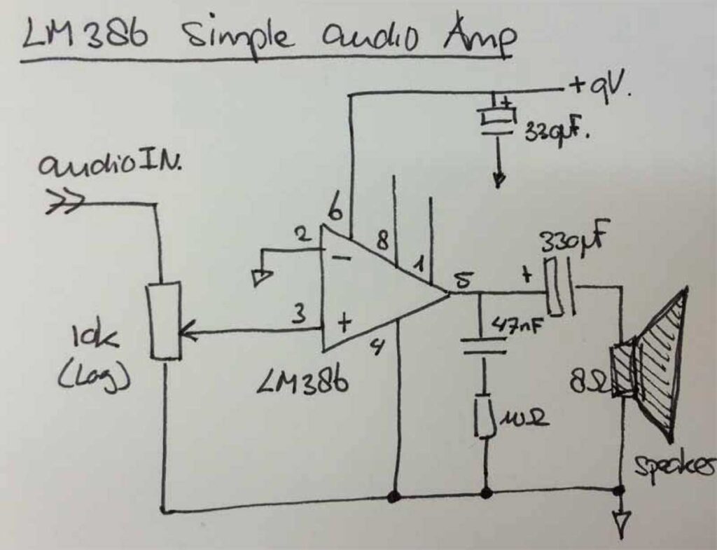
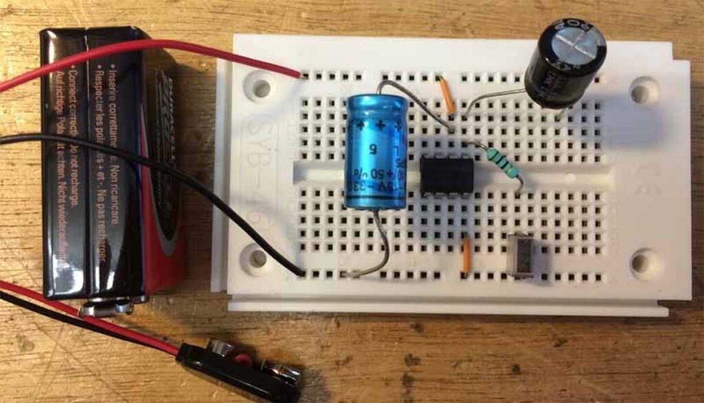
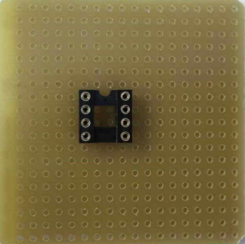
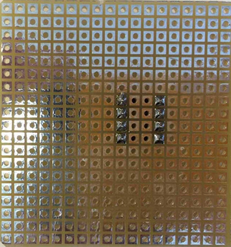
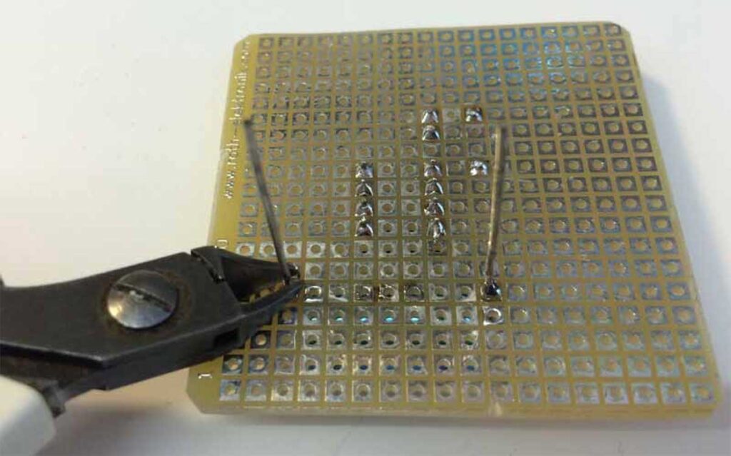
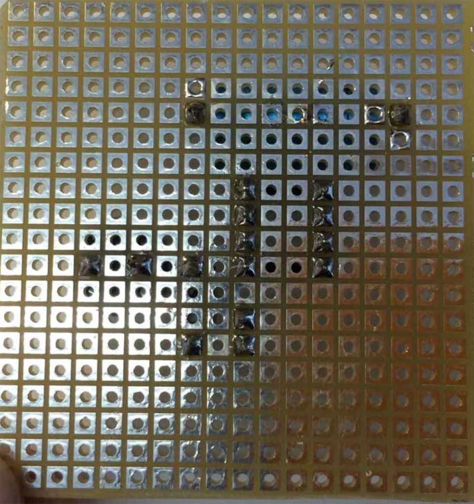
Below an example of how to transfer an experimental circuit (a simple audio amplifier) into a stable printed circuit board.
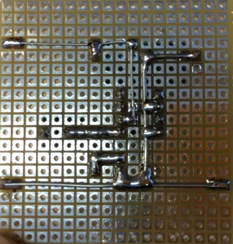
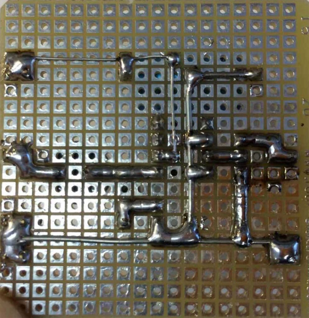
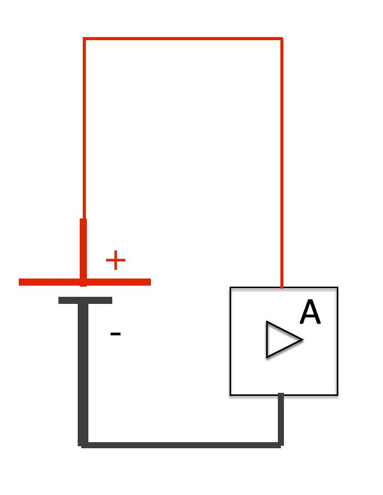
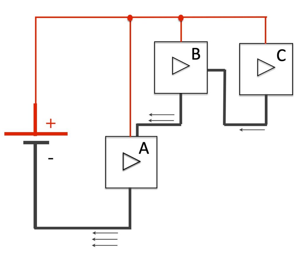
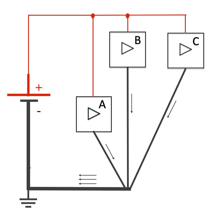
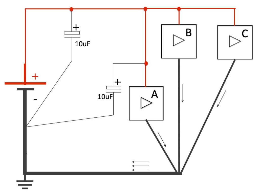
How to connect ‘Ground’
When you connect power to a circuit, use thicker wire for the ground. The ground should always be very LOW IMPEDANT. This means, the resistance should be low. Thicker wire does the job …
Think of the water supply in your house: the water is entering your house through a tube of 14mm, but going out in a big tube. In other words: using thicker wire for the ground, avoids disturbances and unpredictable behavior. Also check how you connect the ground.