Oscillators with CMOS HEF 40106
An oscillator is an electronic circuit, that produces a repetitive electronic signal.
During this last lesson we will experiment with some some simple oscillators. Take a look at the animation on the right. This shows the resonance of a spring/mass combination, in an ‘undamped’ setup; so no losses due to friction. An electronic oscillator is more or less the same. A resistor (R) in combination with a capacitor (C) will also resonate. If we connect the R and the C to an active component (giving it energy to resonate), we have an oscillator.
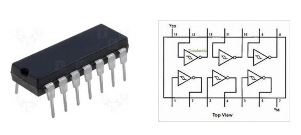
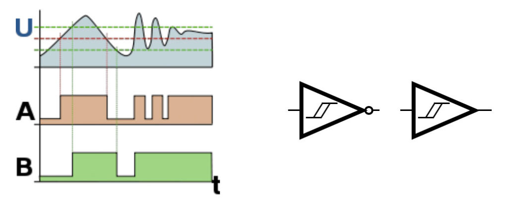
Let’s take a look at the active component that we are going to use: a CMOS invertor, the HEF40106. This is an Integrated Circuit (IC) with six inverters in one package. The 40106 is also called a Schmitt-trigger, because of it’s hysteresis between the in-and output.
Principe
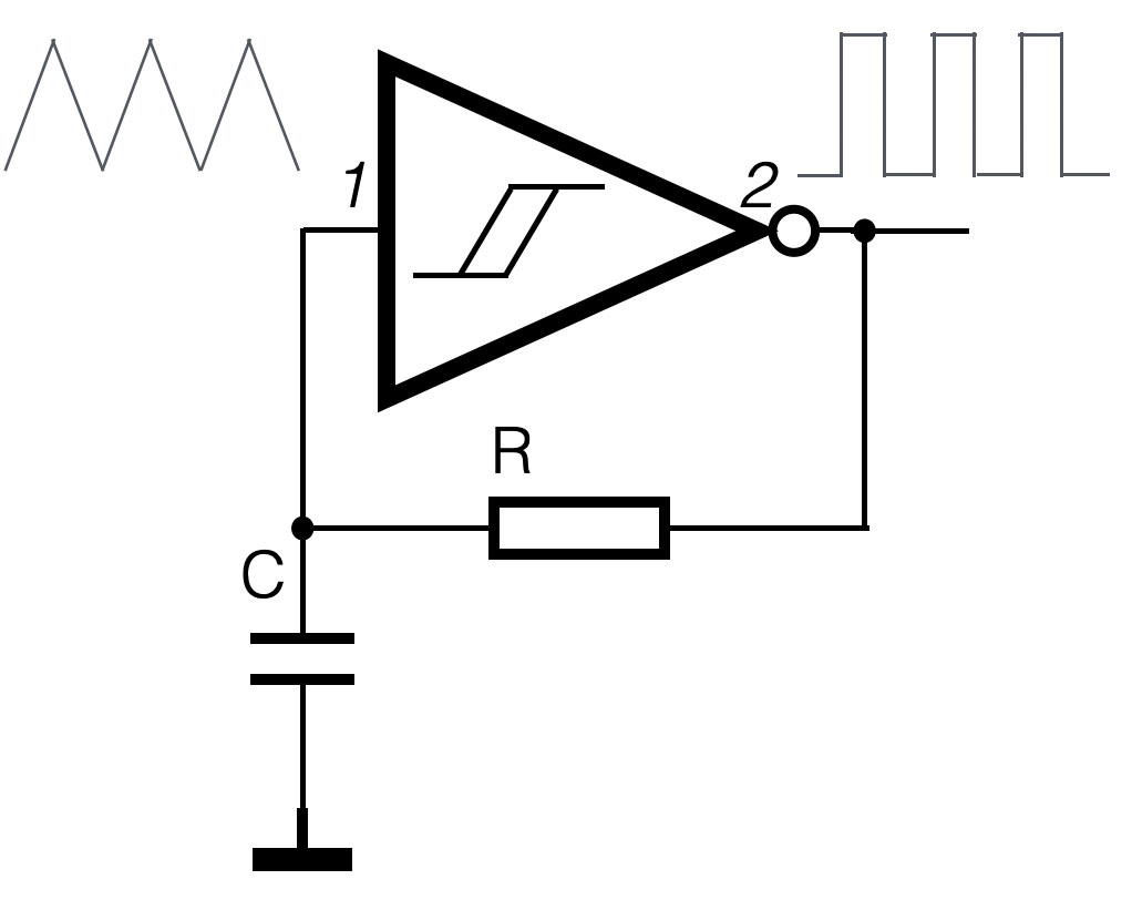
The circuit above shows the simplest setup of an oscillator. How does that work? Pin 2 (the output of the inverter port) is connected to the input of the same port through a resistor R. The input is also connected to a capacitor.
How does that work?
– Suppose the input at pin 1 is 0V (in case of start-up for example), the output will be ‘high’. If the power-supply of the chip is (say) 9V, the output is also 9V.
– At that moment the voltage at pin 2 is higher than pin 1, the current will flow through the resistor R, into the capacitor C.
– The value of the voltage parallel to the capacitor will ‘slowly’ rise above the upper threshold and the output of the invertor will switch from 9V to 0V. Now the capacitor will discharge through the resistor, until the value of the input (pin 1) will drop below the lower threshold – the output goes ‘high’ again (it will be 9V).
– We are back at the beginning and the cycle will keep on going. It will resonate its own static frequency. The frequency depends on the value of the capacitor and the resistor. They determine the ‘speed’ of the proces. The bigger the capacitor and the resistor are, the slower the system resonates, the lower frequency will be
Variations
Based on the principe explained above, there are lots of variations on the same theme. The circuit below has diodes in the feedback part, which will create different pulse width’s.
Master and Slave
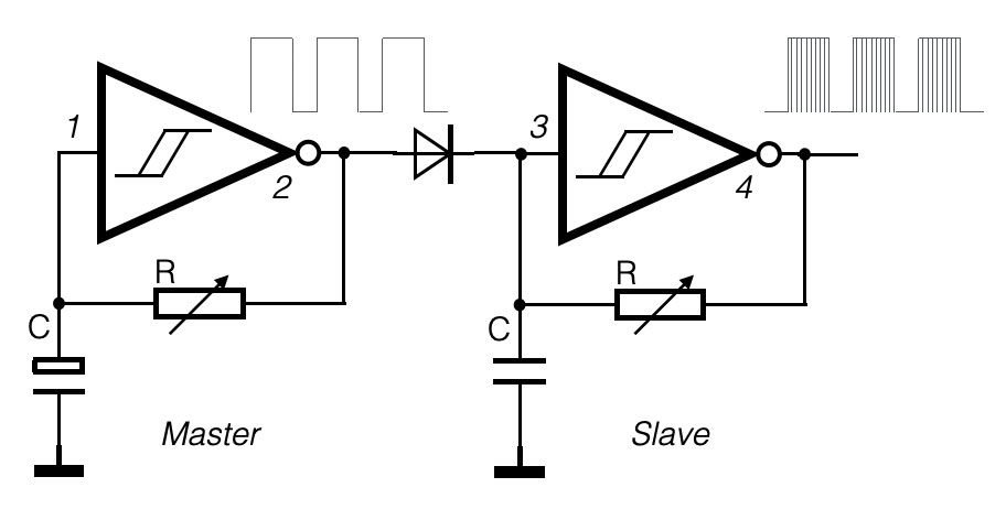
The circuit shown is called a master-slave combination. The ‘ slave’ is only active when the output of the ‘master’ is ‘high’, due to the diode. The capacitor and the resistor of the master have higher values and will resonate on a lower frequency. The ‘slave’ has smaller values and is oscillating on a higher frequency. On pin 4, the output of the slave, the ‘master envelope’ is filled with the signal of the slave. Both resistor symbols do have an small arrow. This means you can use ANY variable resistor you want (LDR, FSR, Potentiometer, Digital potmeter, NTC, …).
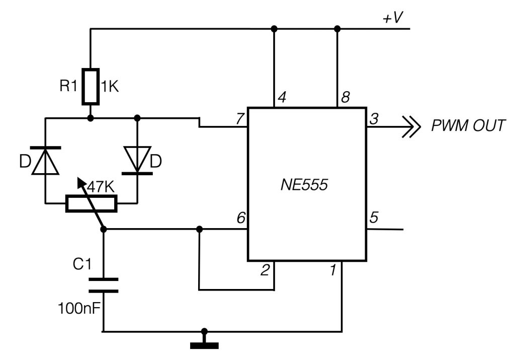
Simple PWM generator
Below an example of a simple PWM generator. Based upon the timer chip NE555, you can relatively easy create a Pulse Width Modulator circuit. With this circuit oyu could (for example) change the speed of a motor, or dim a small light, without using the Arduino.