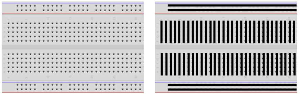
A breadboard is a tool that can help with the electronics experiment. You can try out circuit ideas and rapidly make connections between multiple components. On the left side in picture below you see the standard breadboard layout. Every little hole is a point that can be connected and physically is a sort of clamp that ‘holds’ the wire. On the right side the black lines indicate how the internal hole’s are connected. On the top and below you see 4 horizontal lines. These lines are mostly used for the power supply. In the middle there are multiple smaller vertical columns, each one consisting of 5 holes.
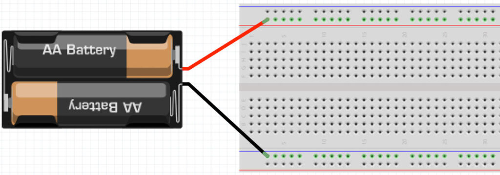
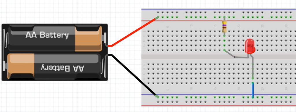
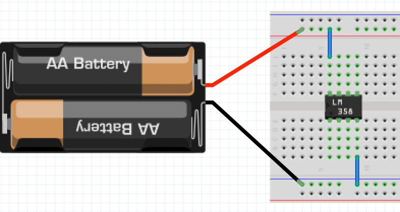
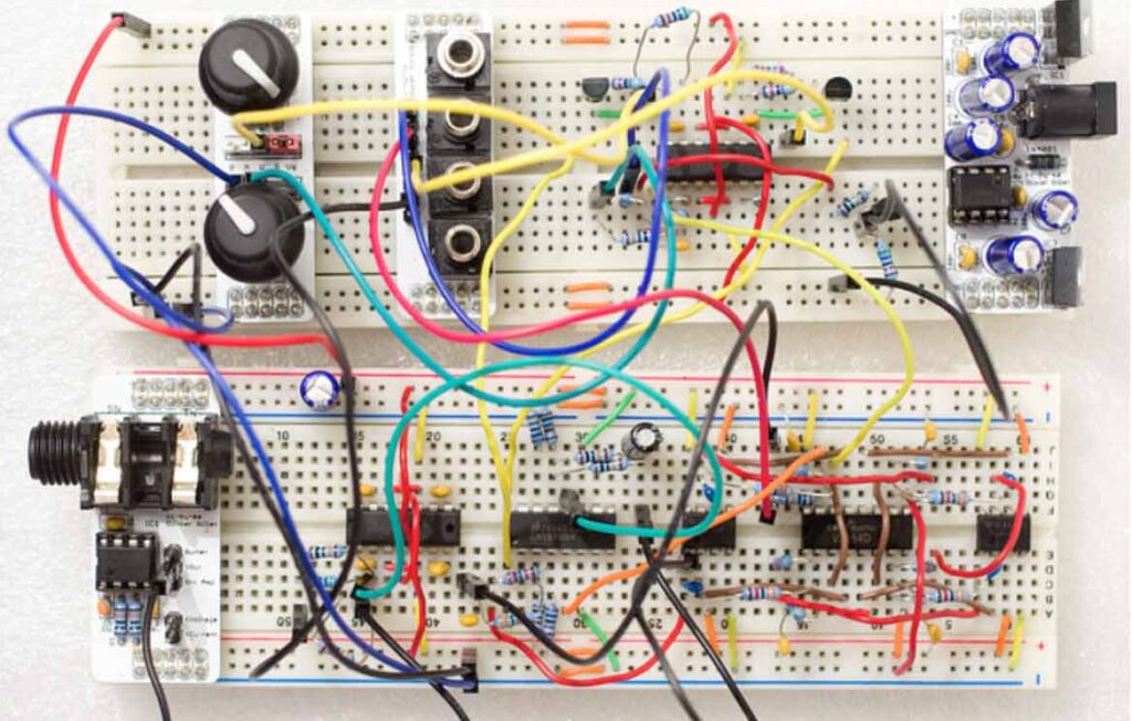
Below some examples how to use the breadboard.