While making all the projects, I’ve been using a lot of different Opamp circuits and actually the basic concept of the circuits used, is often the “same”. In this article I will point out the most important Opamp circuits used in combination with active sensors. These active sensors, like for example the acceleration sensor, produce a tiny DC-voltage change, which has to be amplified and tweaked.
Some fundamentals:
The word “Opamp” is an abbreviation of ‘Operational Amplifier’ and is an ideal building block in electronics. There are 3 fundamental properties:
1. It has a very high input impedance (resistance): so it doesn’t take any current into it’s input.
2. It has a very low output impedance; so it can deliver a relative strong output current.
3. The amplification (Au) is very, very high.
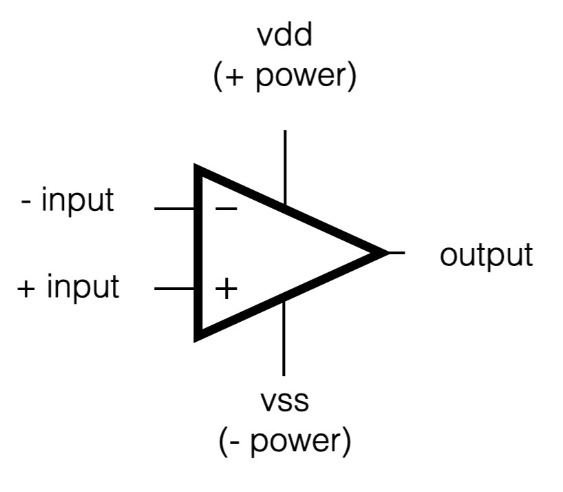
In the circuits below, the power supply of the Opamps is not drawn. If you make use of an opamp, you will always need a power supply to ‘feed’ the opamp. Most of the times, especially in audio world, the opamp needs a balanced power supply, meaning +voltage, ground and -voltage. When I work with sensors, I do use Opamps that also work with a single power supply (+voltage and ground). For example: LM358, TLC274, LM324. For more information about the opamp itself, checkout the wikipedia or equivalent websites.
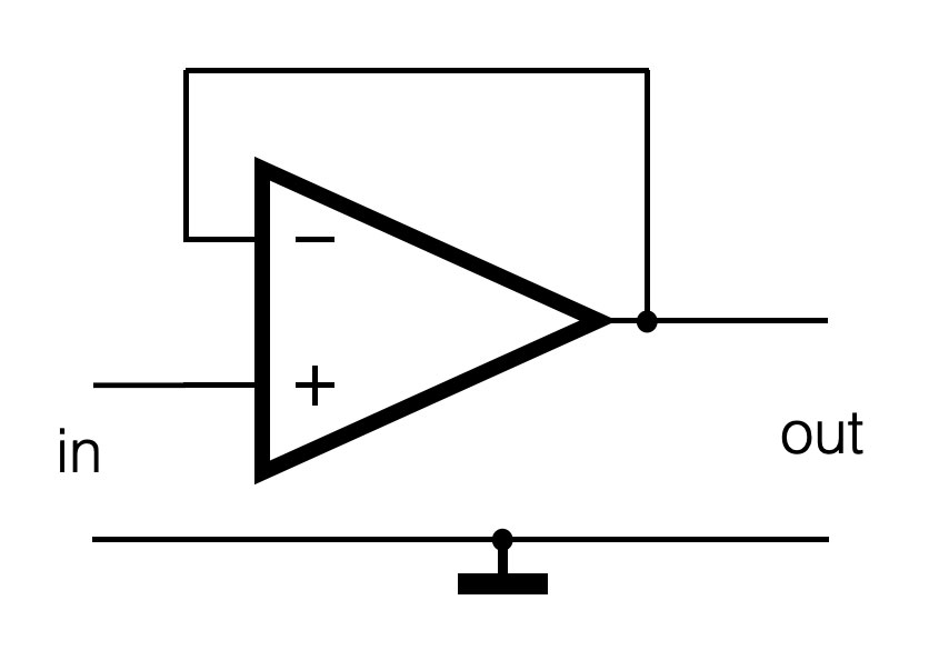
Follower or Buffer circuit:
This circuit is used to ‘buffer’ the output of a sensor. Often the sensor is placed far from the actual sensor interface, so long wires have to be connected to it. To avoid loss of the signal (the output of the sensor is not always capable of generating enough current), this circuit can be applied. The output of the sensor is connected to the positive input of the opamp. Because of the feedback from the output to the negative input, the Au (amplification) is 0dB, or 1x. The output signal is not amplified, but just ‘follows’ the input. The opamp is capable of driving more current and a somehow longer cable will not be a problem. The sensor just has to deliver it’s tiny current (almost zero!) to the input of the opamp.
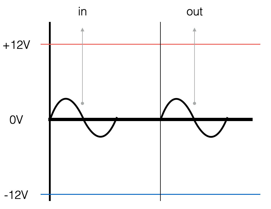
The graph on the right shows the input- and output signal of the follower-circuit. Both the amplitude and the phase of the signals are the same. Note the blue and red line. They represent the power supply lines which are connected to the opamp and thus representing the maximum Vtt (voltage top-top) the opamp can generate.
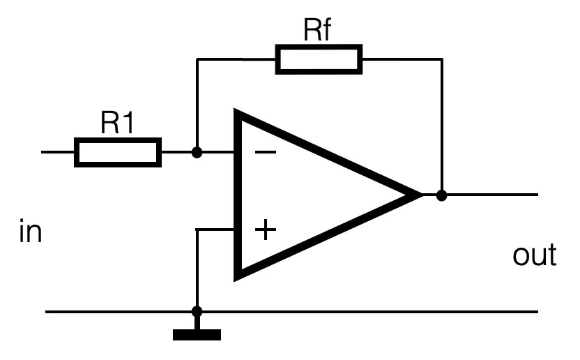
Non-inverting amplifier
The non inverting amplifier has an amplification which is always more than 1x (>0dB). The proportion between the both resistors Rf (R feedback) and R1 determines the amount of amplification. The output of the sensor is connected to the positive input of the opamp.
In formula: (Uout/Uin) = Au = (1+ Rf/R1)
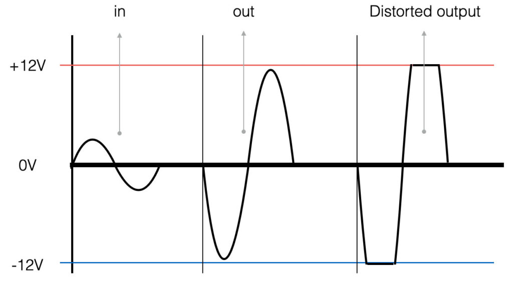
The graph on the right shows the in- and output signal. The amplitude of the input signal is amplified. Note the distorted signal on the right! If the amplification (proportion of the both resistors) is higher than the maximum output swing of the opamp (Vtt), the signal will ‘clip’ and the shape of the signal will change (be distorted).
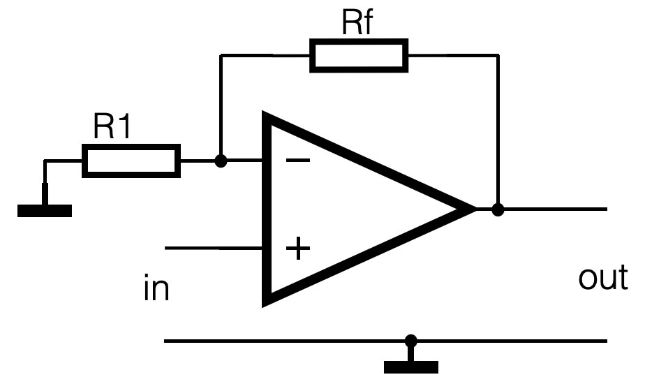
Inverting amplifier
The amplification (Au) with the inverting amplifier only depends of the proportion between Rf (R feedback) and R1. The output is 180 degrees out of phase with the input; it’s negative. This circuit is also known as the summation amplifier.
In formula: (Uout/Uin) = Au = – (Rf/R1)
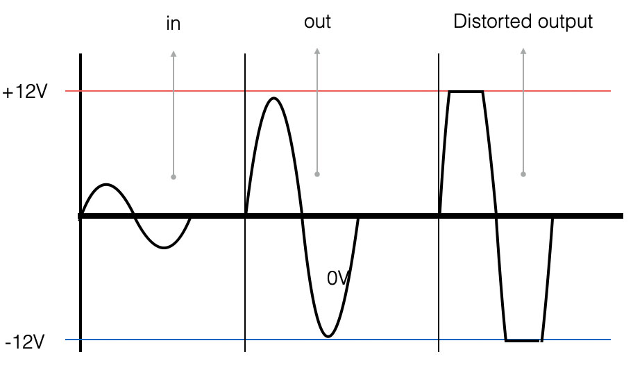
The graph show the output signal inverted, it is 180degrees out of phase with its input. Also here, too much amplification can cause distortion.
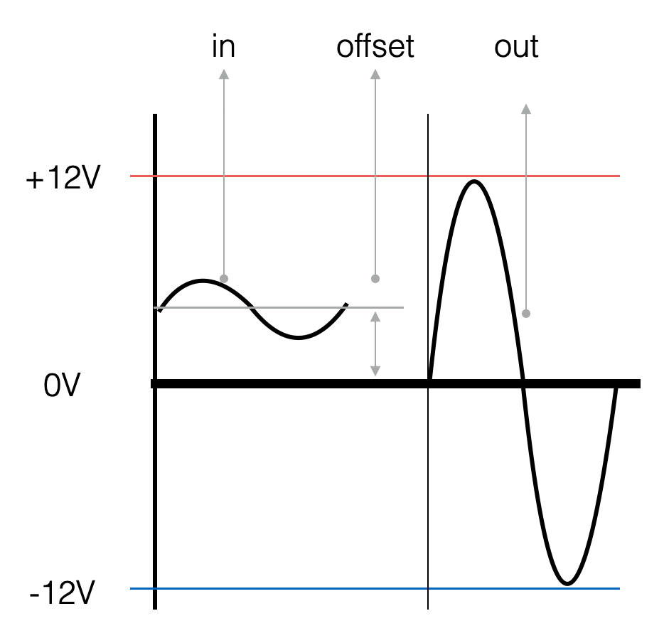
Non inverting amplifier with offset adjustment
A lot of sensors do generate a little DC-voltage change, but do have some DC-offset on the output. With the ADXL202 chip for example, the filtered output is “DC-change” (=AC) in reference to 2.5V. When the sensor is tilted to one side, the output will be 2V and tilted to the other side 3V. This means a maximum change of 1V. It would be better to have the output swing a big as possible – a higher resolution. In the circuit above, the amplification will be around 2,5 -3 times (around 10dB). With the potentiometer connected between the plus and minus power, the output DC-offset can be adjusted to zero.
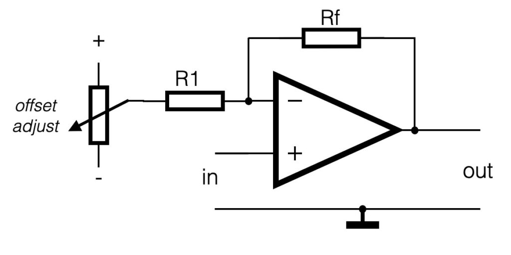
In the picture on the right a graphical representation