Ohms law
Some basics of electronics
To be able to understand a bit more about electronics and the circuits that are shown on this or other websites, it is actually inevitable to understand Ohm’s law – it makes live a bit easier. You have to understand what happens with the current, the voltage and the resistance. All these three variables are linked and make part of ‘Ohms Law’.
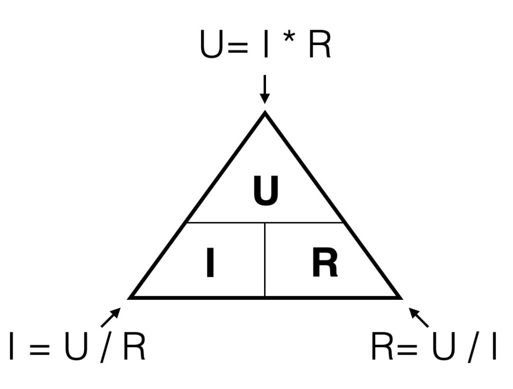
In formula: U = I x R
The voltage [V] is a product of the current {A] times the resistance [Ohm])
A graphical representation of this formula: when you look to the triangle from one of the three angles, you ‘see’ the formula’s for every variable. If you look from the top you ‘see’ U = I*R. Looking from the left corner beneath, you ‘see’ I=U/R.
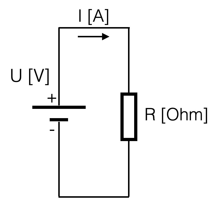
In other words: the higher the value of the resistor, the lower the current given a constant voltage (the battery). If the resistance is 0 Ohm, we call this a short-circuit. A short circuit will result in a undefined value (too high) of the current (dividing by zero is not possible)
Suppose you have a battery of 9V. If you connect a resistor of 1kOhm (=1000 Ohm) parallel, the resulting current will be:
I = (U / R) = 9 / 1000 =
9 mA = 0,009 Ampere (A) (9 mili Amp)
Within electronics, the values we use will vary from Tera (= 1000000000000) or 1012 ( a one with 12 zero’s) to pico: 0,000000000001. The engineering values always take steps of ‘3’ digits, in order to keep the notation clean and avoid errors.
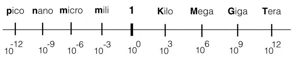
Check this link for ‘The Scale of the Universe’.
Series
Voltage divider
If resistors are placed in series (see figure below), the total resistance is a summation of al the resistors. So the total resistance in the example below is: R1+R2. If more resistors are placed in series, just add them up. If you have the total resistance, the current can be calculated in that circuit with ohm’s law.
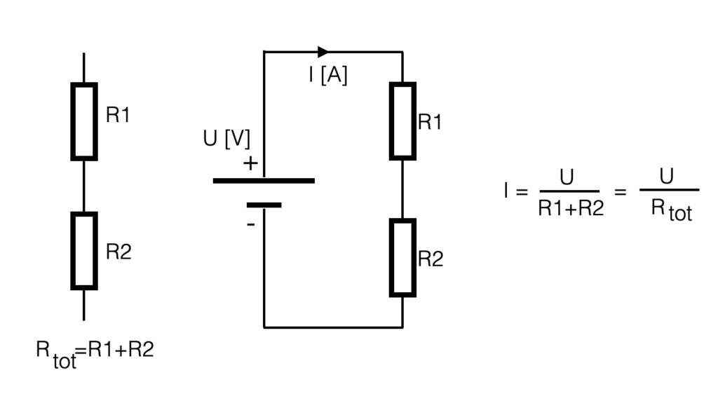
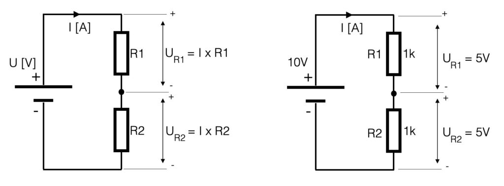
The current (I) in the series-circuit (see above) is the same in the whole circuit. There is only one branch. The voltage however is divided into equivalent parts. Another name for the circuit above is a voltage divider. The current through a resistor causes a ‘voltage-drop’ so with two resistors the voltage is divided into two values. If the series resistors have the same value (let’s say 1k), the value of the voltage parallel to the resistors is the same – the voltage is divided in equal parts. In case of the example below, the 10V of the power-supply is divided into two times 5V.
Be aware of the values that you use with these kind of calculations. Try to make use of the ‘engineering-values’ and avoid shifting comma’s. See the figure below.
If we would look at the series circuit defining an input and an output, the battery is the input and the voltage parallel to R2 is defined to be the output. This is an important definition when we start to talk about filters!
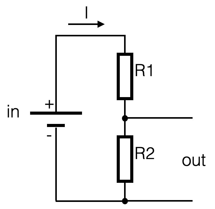
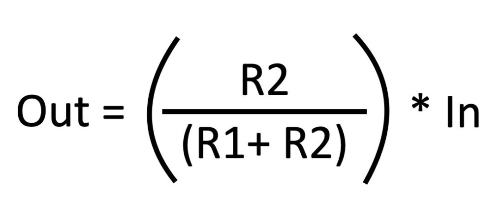
The output of this series-circuit can be defined like this:
Parallel
Current divider
If resistors are placed parallel (see figure below), they divide the current in equivalent parts – hence the name current divider. The voltage parallel to the two resistors is for both resistors the same – it is one electrical node (= electrical point). The current however is divided into two separate current flows. The amount of current is determined by the value of the resistor. See the figure.
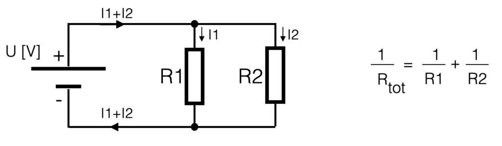
The total resistance of parallel resistors is the inverse of the series switched resistors. To calculate the total resistance you have to sum the inverses. This means that when resistors are connected parallel, the total resistance will go down. Suppose we have 2 resistors of 1kOhm placed parallel, the total resistance will be 500 Ohm.
Quiz question 🙂
Below a circuit with series and parallel connections. The voltage of the battery is 10V dc. All resistors have the same value of 1K Ohm. The quiz question is: what is the voltage parallel to resistor R4? Good-luck!
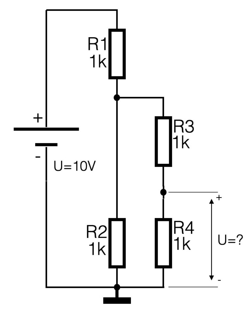
PS: the symbol on the bottom of the circuit indicates the ground connection.