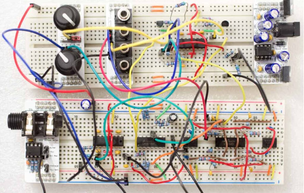
If you want to experiment with electronic circuits, a breadboard can really be of great help. Of course you can directly start with soldering components and wires togehther, but if you are not sure about the design, it’s very convenient to “connect and re-connect” without soldering hassle.
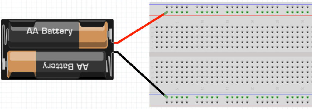
A breadboard is nothing more than a few metal strips with ‘clamps’ organized in a way that it is easy to make an electronic circuit. Take a look at the picture below. On the top and the bottom you see two horizontal lines. All four of these lines are separate electrical points (or nodes). These lines are mostly used to distribute the power of (for example) a battery. In case of the example below the plus line is connected to the upper hor. line and the minus to the lower hor. line.
The vertical shorter lines in the middle also represent separate nodes.
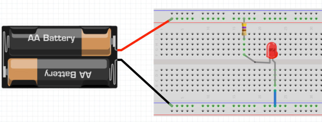
Below an example of the connection of a battery, a series-resistor and a LED.
The breadboard is designed to also connect IC’s (Integrated Circuits). This is the reason why the upper vertical lines are not connected with the lower ones. Check this example:
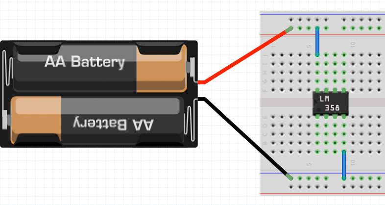
The two pins of the chip (pin 4 and pin 8) are connected to the power lines. You can really create complex circuits on a breadboard.