If you want to check your circuit you need to tools to ‘look’ at your circuit and check whether the values are correct. Is it the right voltage? How big is the current and what is the exact shape of the AC signal? For these measurements you need tools.
Multimeter
The most common tool to measure values in a circuit is the multimeter. With a multimeter you can measure the voltage (AC or DC), the current (AC or DC), the resistance and depending on the model also the capacity or some semi-conductor values.
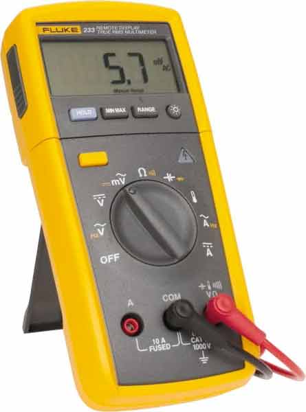
Another important feature is the ‘beep’ function. With this function you can check the connection between two points. It has the symbol of a diode – it is a diode check function at the same time.
Important to know is the following: when you measure the voltage (V) in a circuit you always do this parallel (see the picture below). This means the resistance between the two measuring clips is ‘infinitely’ high – otherwise the multimeter would influence the behavior of the circuit and that is not acceptable.
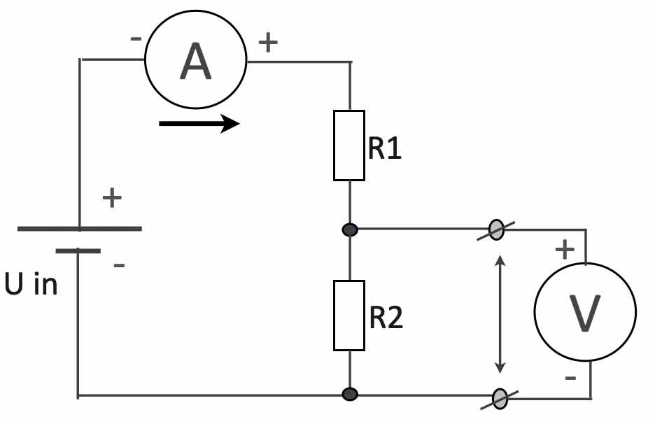
As shown in the ‘voltage divider’ circuit above, the current (A) is measured in series. The current flows through the multimeter and therefor the resistance of the multimeter in current-mode is 0 Ohms.
Component tester
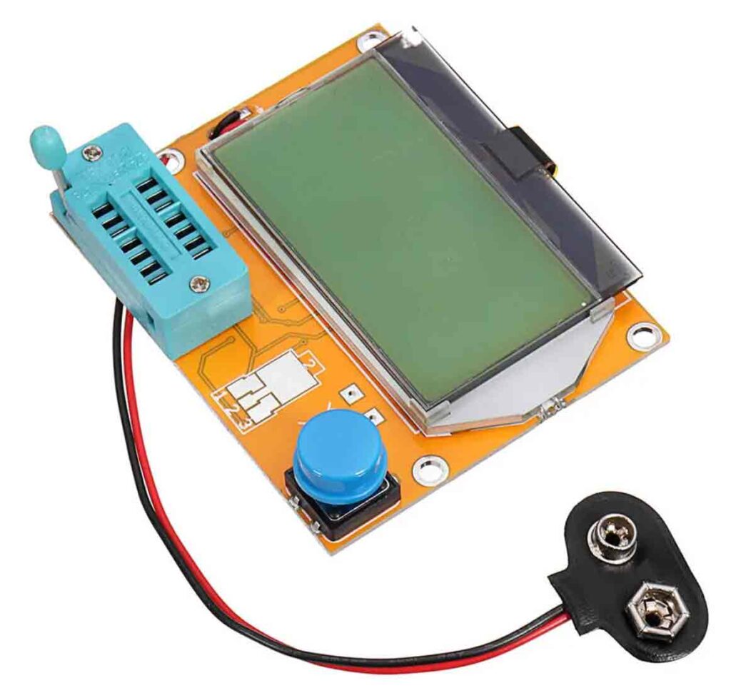
One of the tools that really is practical and cheap, is the component tester shown below.. With this tester you can determine the value of a resistor (ignoring the colour codes:), test the values of capacitors. coils, transistors and fet’s. Very practical.
The oscilloscope
The oscilloscope is the main measuring tool to help you ‘look’ at the signals within the circuit. The screen is divided into small block called Divisions. Most of the oscilloscopes have two inputs. This way it’s easier to compare signals with each other.
The most important keys on a scope are the “Volt/Division” setting the vertical value of the signal and the Time/Div knob setting the horizontal value. Depending on the value the knobs are indicating, the value of the signals can be read. Below a picture of the oscilloscope we will use during the lessons.
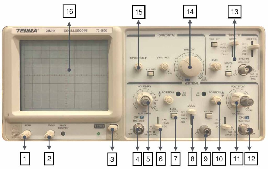
1. Changes the light-intensity of the screen
2. Focus the screen
3. Power On/Off
4. Input channel 1
5. Volts/Div channel 1
6. AC/GND/DC selection
7. Chop/Alternate
8. Input selection Ch1,Ch2, Dual, Add
9. Ground connection
10. Position beam channel 2
11. Volts/Div channel 2
12. Input Channel 2
13. Trigger section
14.Time/Div setting
15. Horizontal position screen
16. Screen with 10 x 8 divisions
Quiz question 🙂
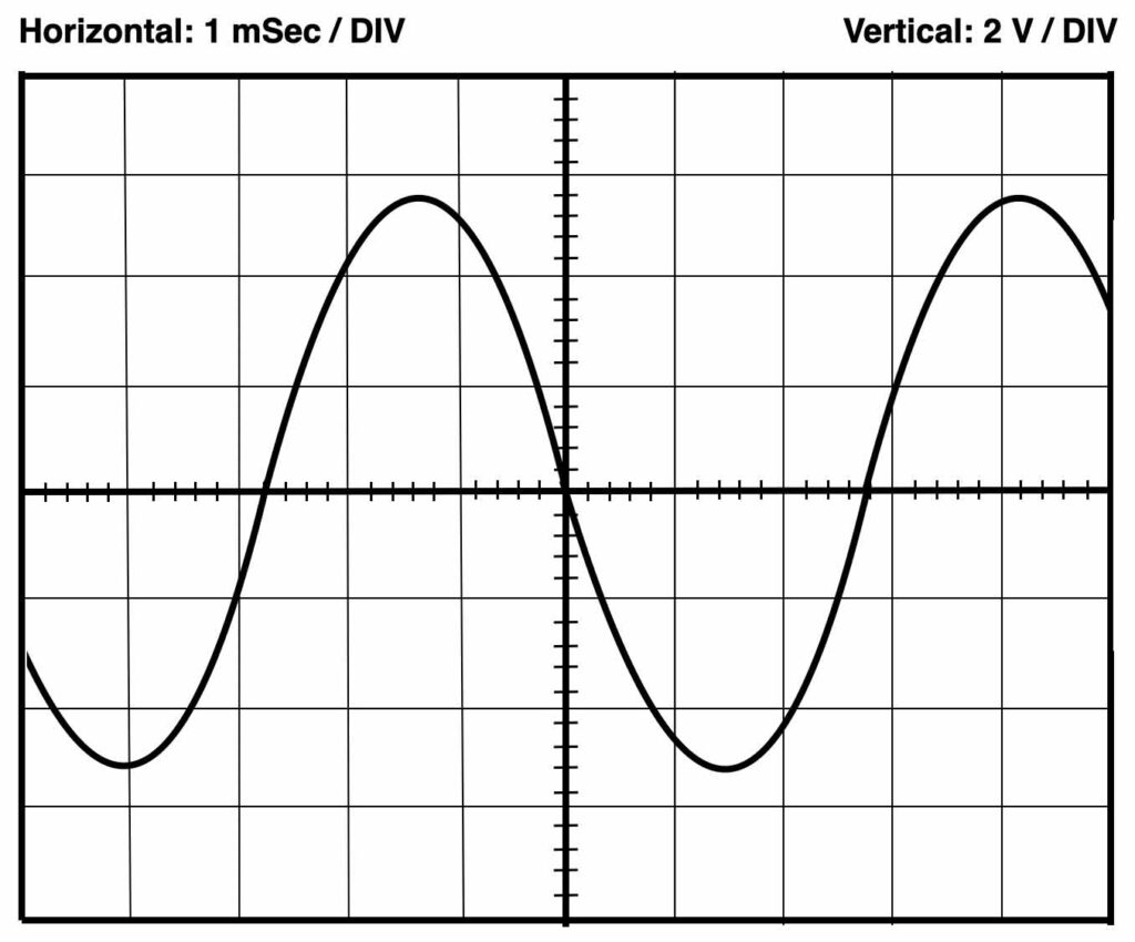
Below a sample screen of the oscilloscope. Can you determine the right frequency? The Volts/Div and Time/Div settings are indicated on top.