When movement is detected, this thing needs to go on for three seconds after which it should not be triggered for ten seconds. But if nothing happens in two minutes, it should trigger by itself. How?
Question posed by a random colleague student
The global behaviour of an installation based on a microcontroller, often includes timed processes. For instance, after a trigger, the input is blocked for a certain amount of time; if nothing happens for a while, generate an event; if within a certain time span a second trigger is sensed, change the behaviour; etc.
The most fundamental blink example suggests that timing can be controlled with a delay() function. However, the delay() has a fundamental issue which renders it useless in all of the situations described above: the program will proceed to the next line of code only when the wait is finished. In other words, during a delay(), all processing comes to a standstill. The function delay() could as well have been called holiday(). Therefore, ditch the delay().
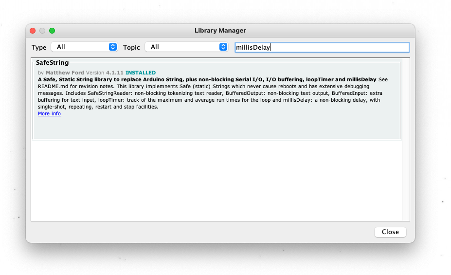
The blink without delay and debounce examples introduce an approach to timing using the millis() function. It is an approach in which the passing of time is measured based on an onboard clock. When multiple overlapping time units are involved, this approach tends to become complex and difficult to manage. An alternative solution can be found in using the millisDelay statement, which is part of an external library. This library can be found and installed through the Manage Libraries… menu option.
Detecting State Change
In order to connect an action to sensor input, it is important to be clear about what is the difference between a sensor measurement—e.g. a value from digitalRead()—and a state changement—e.g. when a button is pressed, while before it wasn’t. Sensor measurement produces a stream of values, while a state change should be able to detect the moment at which a button is pressed. A stream of values is what is produced in the Digital Read Serial example.
In order to detect a state change, the code needs to be extended in such a way that the current state can be compared with the previous. When considering that what is defined in the loop() routine represents a single lifespan of the loop, something needs to be handed to the collective unconsciousness—or, in terms of Arduino code, a global variable—before the current run of the loop dies in order to be retained.
Here the order of things can be explained as follows. At the moment the button is pressed—nowClosed is true—while before it wasn’t—beforeOpen is true as well—the if statement checking these two booleans will execute the first section. The LED turns on and the serial monitor prints “switch closed”. At the moment the button is released, momentarily the else if sees it’s conditions met and will execute the connected block. All other cases are neither of these two options and are disregarded.
The last line—beforeOpen = !nowClosed—although it appears a bit cryptic is the crucial bit of information that becomes available the next time the loop runs: beforeOpen will become true if nowClosed is not true. We could consider this the will of the current loop that dictates the heritage of the next loop.
const int ledPin = 13;
const int switchPin = 2;
bool beforeOpen = true;


void setup() {
  pinMode(switchPin, INPUT_PULLUP);
  pinMode(ledPin, OUTPUT);
  Serial.begin(115200);
}

void loop() { // loop is (re)born
  bool nowClosed = digitalRead(switchPin) == 0;
  if (nowClosed && beforeOpen) {
    digitalWrite(ledPin, HIGH);
    Serial.println("switch closed");
    delay(5); // lazy debounce
  }
  else if (!nowClosed && !beforeOpen) {
    digitalWrite(ledPin, LOW);
    Serial.println("switch open");
    delay(5); // lazy debounce
  }
  beforeOpen = !nowClosed; // update global variable for next loop
} // loop dies
Temporarily Block Sensor Input
The state change introduced in the previous example, will be used here to connect specific actions. When the button is pressed, it will activate a timer that blocks the detection of the on state for a certain amount of time. Releasing the button will have no meaning in this context and the action connected to that can be removed.
The timer is created using the millisDelay.h library, and a delay is created using the millisDelay ledDelay statement. This ledDelay becomes a reference to a mechanic that is running in the background, that can measure time. A trigger is sent using ledDelay.start(LED_time), where LED_time specifies the amount of milliseconds it will take before ledDelay returns the trigger, signaling the end of the delay. This end trigger needs to be queried using the ledDelay.justFinished() statement, which will become true when this is the case. Until this happens, input by the button will be blocked.
#include <millisDelay.h>

const int ledPin = 13;
const int switchPin = 2;
bool beforeOpen = true;
bool blocked = false;
int LED_time = 2000;
int switchCount = 0;

millisDelay ledDelay;

void setup() {
  pinMode(switchPin, INPUT_PULLUP);
  pinMode(ledPin, OUTPUT);
  Serial.begin(115200);
}

void loop() {
  bool nowClosed = digitalRead(switchPin) == 0;
  if (nowClosed && beforeOpen && !blocked) {
    Serial.print("switch closed ");
    switchCount += 1;
    Serial.println(switchCount);
    digitalWrite(ledPin, HIGH);
    ledDelay.start(LED_time);
    blocked = true;
//    delay(5);
  }
//  else if (!nowClosed && !beforeOpen) {
//    Serial.println("switch open");
//    delay(5);
//  }
  if (ledDelay.justFinished()) {
    digitalWrite(ledPin, LOW);
    blocked = false;
  }
  beforeOpen = !nowClosed;
}
Auto-Trigger
A second millisDelay is added in order to automatically trigger the process—following the requirements posed in the top section, although for testing the time for this is reduced to 10 seconds.
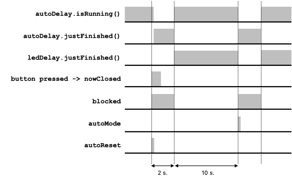
When the Arduino starts up, this second delay, which refers to the autoMode flag, is triggered. Now there are two options, either the button is pressed before ten seconds pass, or isn’t. In the first case the autoDelay will be stopped; only when the button was pressed autoDelay.isRunning() will be true. Since later on in the code we will check whether the autoDelay.justFinished(), the autoReset flag is used to indicate that a reset has happened because of an activation, instead of time running out.
In the second case, the autoMode flag is raised so an activation can take place. The overview below shows how these flags are raised and lowered either because of a button pressed or the ten seconds auto trigger.
#include <millisDelay.h>

const int ledPin = 13;
const int switchPin = 2;
bool beforeOpen = true;
bool blocked = false;
bool autoMode = false;
bool autoReset = false;
int LED_time = 2000;
int auto_time = 10000;
int switchCount = 0;

millisDelay ledDelay;
millisDelay autoDelay;

void setup() {
  pinMode(switchPin, INPUT_PULLUP);
  pinMode(ledPin, OUTPUT);
  Serial.begin(115200);
  autoDelay.start(auto_time);
}

void loop() {
  bool nowClosed = digitalRead(switchPin) == 0;
  if (nowClosed && beforeOpen && !blocked || autoMode) {
    digitalWrite(ledPin, HIGH);
    ledDelay.start(LED_time);
    if (autoDelay.isRunning()) {
      autoDelay.finish();
      autoReset = true;
    }
    switchCount += 1;
    if (Serial) {
      Serial.print("switch closed ");
      Serial.println(switchCount);
    }
    blocked = true;
    autoMode = false;
  }
  if (ledDelay.justFinished()) {
    digitalWrite(ledPin, LOW);
    blocked = false;
    autoDelay.start(auto_time);
  }
  if (autoDelay.justFinished()) {
    if (!autoReset) {
      autoMode = true;
    }
    autoReset = false;
  }

  beforeOpen = !nowClosed;
}
…