The fundamental digital ports
In the digital-electronics world it all is about ‘ones’ and ‘zeroes’. It’s about ‘Yes’ or ‘No’. There is no ‘Maybe’! Computers work with digital data that only consists of bits and combination of bits, called bytes. A bit can only have two values: ‘0’ or ‘1’. In electronics this means 0V or 5V (TTL). Since the development of mobile technology, nowadays lots of computers (e.a. phones) work with 3.3V logic.
The fundamentals of digital electronics starts with the different logic ports called NOT, AND, NAND, OR, NOR , XOR and XNOR. With combinations of logic ports, complex logic function’s can be created. If a lot of these ports are combined (millions…) in one chip, microprocessors and computers are created.
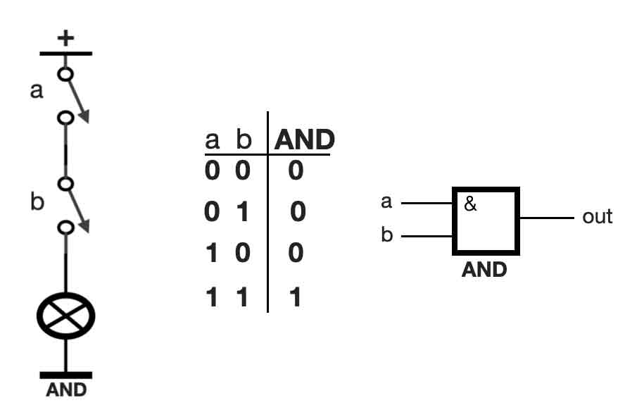
AND port
Let’s start with the basic port called AND. An AND port can be seen as two switches that are connected in series. See the figure below, the left side. If both switches ‘a’ and ‘b’ are OFF (also referred to as 0), the lamp (the circle with the cross) will not light up – it’s also OFF (= 0). If switch ‘a’ is ON (= 1), and switch ‘b’ is OFF (= 0), the lamp is still OFF. We can put these different values in a so called truth table, see the tabel in the middle.
On the right side the European symbol of an AND port is shown.
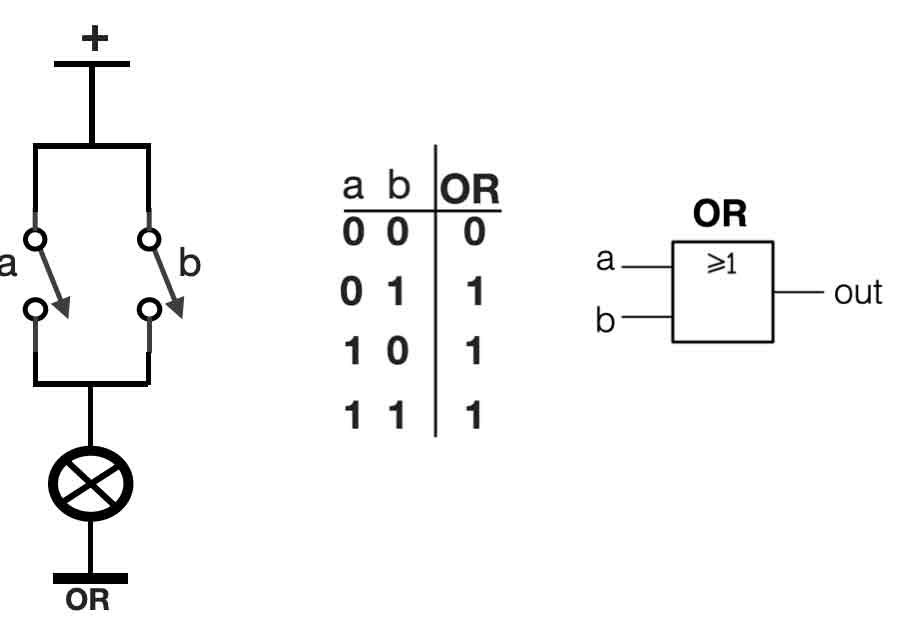
OR port
An OR-port is a combination of two switches connected parallel. See the left side of the figure. This gives another truth-table. If only one switch ‘a’ or ‘b’ is in the ON position ( = 1), the outcome will be 1. See the figure below:
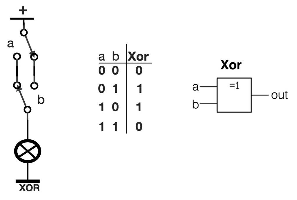
XOR-port
The XOR-port is also called an ‘Exclusive OR’ port. This port consists of two switches both with two poles. The setup of this two switches is that with both of you can switch the light ON or OFF. This circuit is often applied in rooms where you can switch the light ON at the door and switch the same light OFF on the other side of the room – it’s practical. Take a look at the figure below. In the XOR-port the light is only ON when both switches ‘a’ and ‘b’ are in the oposite position. In case of the picture below the switches are in the same position (upside down) – thus the result is “0”.
A port overview
All the ports mentioned above also have their ‘INVERSE’. This means the opposite of the values in the normal state. For an AND the inverse is called a NAND. An OR port inverted version is called a NOR and a XOR inverted is a XNOR.
There are also ports that only invert – so called inverters. A logic ‘one’ on the input creates a logic ‘0’ on the output and vice versa – always the inverse. There are even ports that do not change the state of a signal. In other words, a logic ‘0’ on the input creates also a logic ‘0’ on the output. These ports are called buffers.
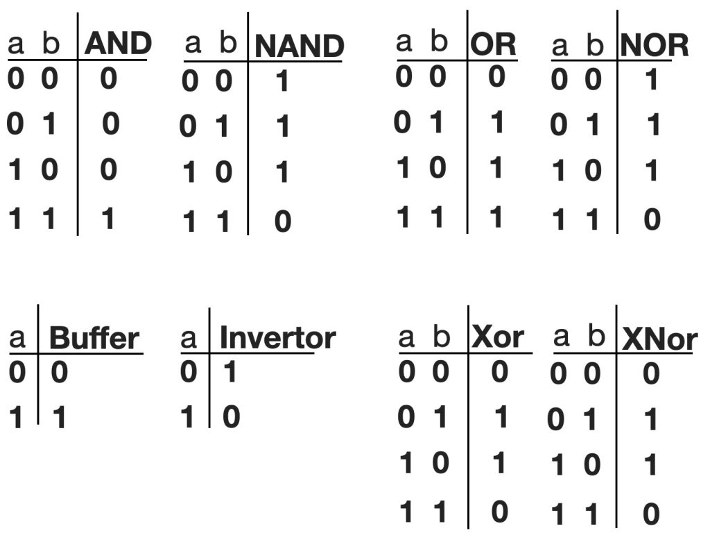
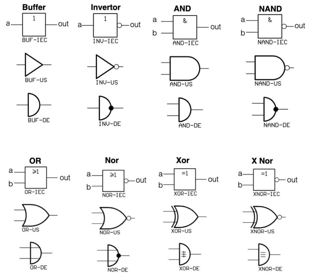
And below an overview of all the symbols of the logic ports. In Europe and the USA they use different kind of symbols – for the same logic ports. This can be confusing.
Binairy counting and resolution
With the logic ports mentioned above a lot of great functions can realized. Like decimal counters, dividers, binary counters, shift registers and much more.
So what is counting in the digital world? How can we count and make big numbers with with only 2 bits? First of all we need to use the binary counting system. This system only has two symbols (binary) a ‘0’ and a ‘1’. Our decimal system has 10 symbols (dec). We start with 0 and count till 9. After 9 we combine the first two symbols 1 and 0 , making 10. The same mechanism we apply to binary counting. Starting with 0, 1 and the combine the first two: 10. After that we get 11 and then we combine again: 100.
Take a look at the table below. On the left side the decimal numbers 0 – 15. In the middle the equivalent binary numbers starting with 0000 (=0 decimal) and ending with 1111 (= 15 decimal). So with a 4 bit ‘resolution’ (= 4 bits = 24) we can make numbers from 0 to 15 (equal to 16 numbers, zero included). If we double the amount of bits (=8 bits = 28) we can make numbers between 0 and 255. The higher the resolution, the higher number-range can be made. If we talk about 8 bits, we could also call this one byte.
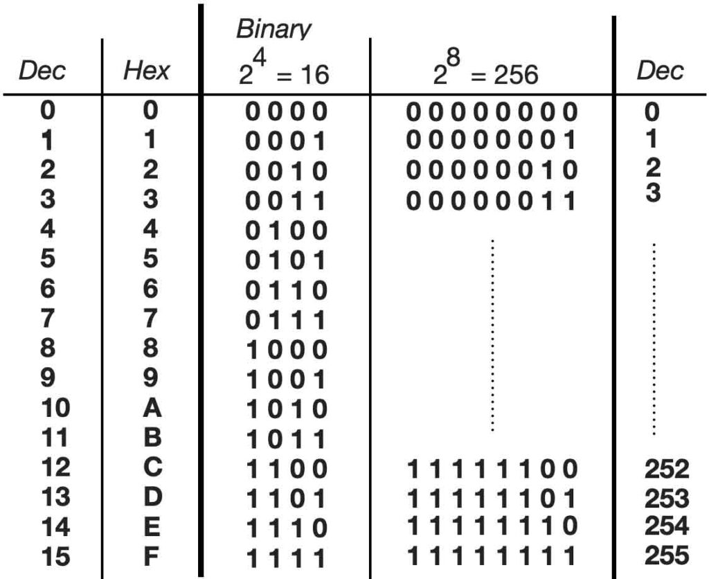
When we take a closer look at the binary series in the table above, you can see that the most right ‘bit’ constantly changes between 0 and 1. We also call this bit the LSB (= Least Significant Bit). The next row is changing every two numbers: 00 11 00 11 … (division by two). The third row is again divided by two: 0000 1111 0000 1111. The fourth again, etc etc. The row on the most left side we call the MSB (most significant Bit). When we create ‘dividers’ with the logic ports, we can create binary counting. Take a look at the figure below.
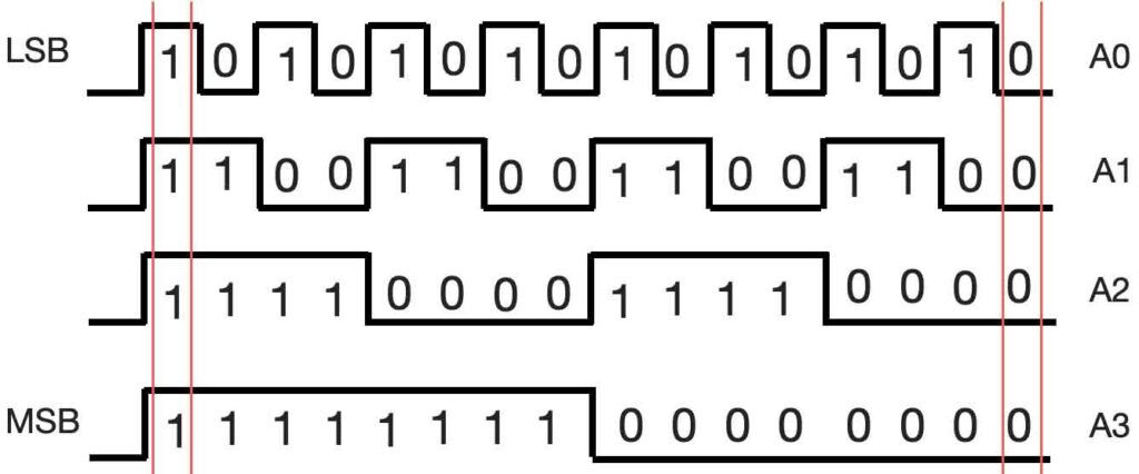
The upper row is the LSB, changing constantly between 0 and 1. The row below (A1) is divided by two resulting in 00 11 00 11… If we look at the numbers on the right side, from top to bottom, we see 0000 (=dec 0). One pulse to the left we see 0001 (=dec 1). Completely on the left side we see 1111 (=dec 15).
There are a lot of different digital ‘chips’ available with already pre-made logic functions. The most common range is the 7400 range and the 4000 range. The 7400-series is so called Transistor Transistor Logic (TTL) and can only with +5V (=1) and 0V (=0). The HEF4000 series is based on MOS (Metal Oxide Semiconductor) and can handle a voltage range between 3 and 18V (depending in the specifications).
More information about digital electronics, check this.