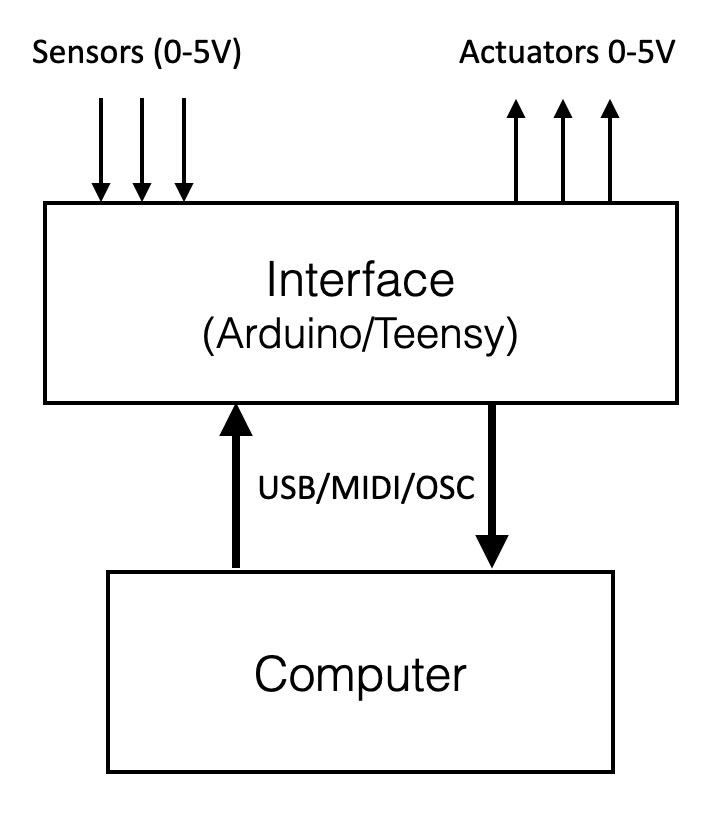
Generic overview
Sensors exist in a lot of different shapes and types. They are all specially made to measure that specific ‘variable’ which they are designed for. A sensors ‘senses’ or measures a physical quantity (e.a. temperature, light, pressure etc) and converts this to electrical signals (resistance, voltage or current). A sensor interface like Arduino, Teensy or IpsonCompact, convert incoming voltage-change into a stream of digital numbers (midi or OpenSoundControl).
So if a sensor only has change of resistance, this has to be converted to voltage change. Or when a sensor generated a tiny little voltage change ( 100mV-200mV) than we have to amplify.
Actuators are the ‘opposite’ of a sensor. By generating “driving voltage” with a computer (sensor interface) external processes can be driven (e.a. dc motor) with an actuator.
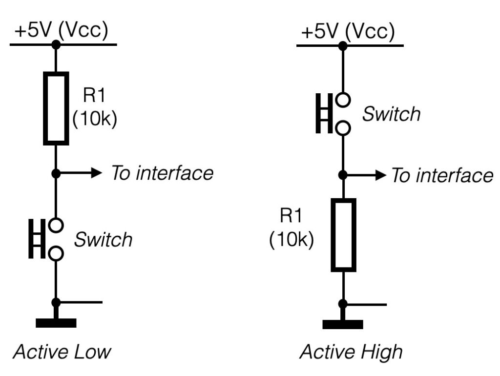
Switches (digital input)
Switches provide a digital input (only 0V or 5V and nothing in between) and can be hooked up to the interface like the configurations shown below. The active low configuration on the left (the switch makes a connection to the ground if it is pushed – the figure on the left), is the preferred method for connecting switches. If you are using a normally open (N.O.) push-button switch, when the switch is pressed, it will send a low level (0V) to the terminal (thus the term “active low”).
On the right side the active-high’ configuration. At the moment the switch is pushed (makes contact), the signal to the input of the interface is pulled up. In other words it changes from 0V to 5V.
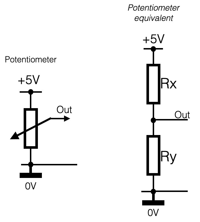
Potentiometers
A potentiometer (or “pot”) can be used to provide an analogue input (= continues changing voltage values) to an input terminal. Using the configuration below, a pot will vary the input voltage to the terminal from 0 – 5V. In other words, the full input range of the terminal. 10k is a typical value for use in this configuration, but anything from 1k to 1M should work fine.
On the right side of the figure below the equivalent circuit of a potentiometer is shown. In fact the potentiometer is the same as a voltage-divider circuit Rx and Ry, where the value of the both resistors depend of the position of the pot.
Resistive sensors
Resistive sensors, such as photo-resistors, force sensing resistors (FSR’s) or flex sensors, can be wired in either configuration shown below. Using the left configuration (active low), the terminal voltage will decrease with decreasing resistance. Using the right configuration, the terminal voltage will decrease with increasing sensor resistance. Use whichever configuration is most convenient for your application.
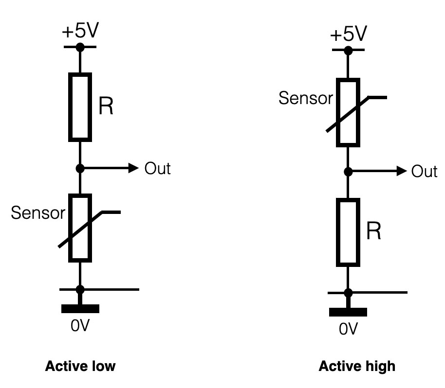
You will also need to select an appropriate value for the fixed resistor R based on the resistance range of your sensor. In general, it is best to select a value for R that gives the largest voltage range for the sensor. The optimal value is R = sqrt(Rmin * Rmax); that is, the square root of the sensor’s minimum resistance times the sensor’s maximum resistance. Once you compute the optimal value, select a standard resistance value that is closest to it. This will give the maximum voltage range for your sensor and thus the best resolution. Use the input min. and max. adjustments for the terminal to compensate for voltage offsets, as described above in the section Analogue input mode details