The MSC workshop will be hosted by two teachers, Johan van Kreij and Lex van den Broek. The course is mandatory for the Sonology Bachelor 2 (B2) group and it will consist of two intensive workshop weeks (2 x 5 days), one in the autumn and one in spring. During these workshops we will talk about sensors, actuators, coding, digital-and analog- electronics and we will guide the participants with their Musical Controller Project assignment.
The goal of the workshop is to discover more about the the technology behind musical-instruments and controllers and to be able to design and create your own instrument and play it!
OSC is a content format developed at CNMAT by Adrian Freed and Matt Wright comparable to XML, WDDX, or JSON.[2] It was originally intended for sharing music performance data (gestures, parameters and note sequences) between musical instruments (especially electronic musical instruments such as synthesizers), computers, and other multimedia devices. OSC is sometimes used as an alternative to the 1983 MIDIstandard, when higher resolution and a richer parameter space is desired. OSC messages are transported across the internet and within local subnets using UDP/IP and Ethernet. OSC messages between gestural controllers are usually transmitted over serial endpoints of USB wrapped in the SLIP protocol
“Introduction to Electronics” for Sonology Ba1 students consists of at least 8 group lessons with an additional small electronic assignment to finish the course. In these lessons we will talk about the most fundamental electronics subjects like: ohms law, AC, DC, frequency, phase, digital, analog, interfacing, sensors, building electronics, power supplies and much more. Also subjects that come along with all the questions you have during the lessons will be part of the content.
Please check the content of this website as well for more information about the different subjects. Check the video page for some fundamentals. The lessons will start Monday september 9th in Sonology studio 6.75 (studio for live Electronic music). Check your Asimut agenda.
Assignment for this course (24-25)
Build your own small (fun) electronic device that actually works!
Some Project Examples
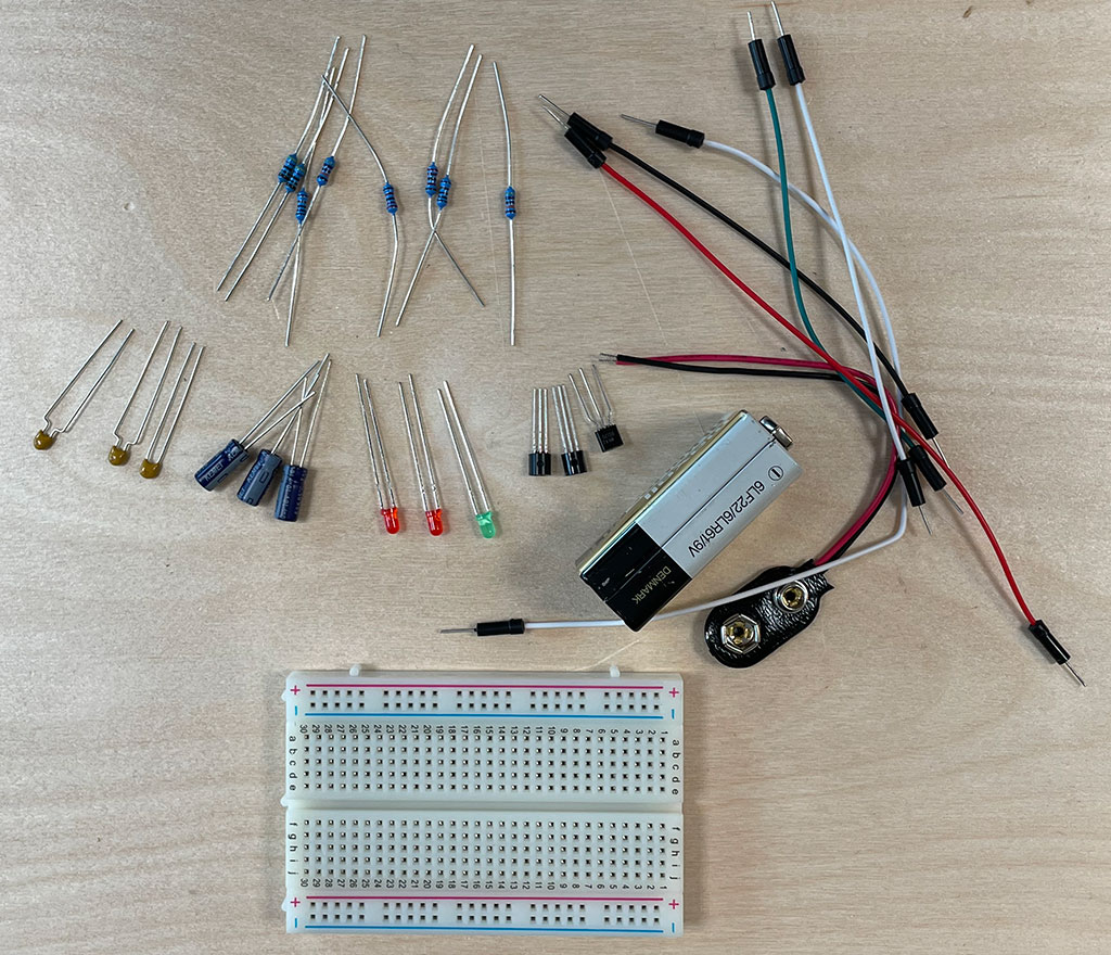
At the start of the first lesson you will all get your own small electronics-kit that consists of the following components:
A small breadboard, 9V battery, battery clip, Resistors: 2 x 10k, 2 x 470k, 2 x 470E Capacitors: 1 x10uF, 2 x 100uF, 2 x 10nF, 2 x 100nF Leds” 2 x Red, 1 x green Semiconductors: 2 x NPN (BC547), 1 x PNP (BC557), 1 x FET (BS170) A few wires
Electronics Starter package
Below you see the PDF ‘booklet’ of the ‘Electronics starting kit” which we will use during the lessons as a nice starting point for building some simple electronics.
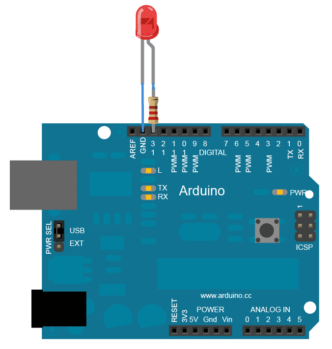
In this page we will learn the basics of serial communication between SuperCollider and Arduino. To start off we’re going to control the brightness of LED from SuperCollider! First, our circuit:
Now, in Arduino upload:
unsigned char val = 0;

void setup() {
  Serial.begin(9600);
  pinMode(11, OUTPUT); // use one of the ~ pwm pins!
}

void loop() {
  if (Serial.available()) {
    val = Serial.read();
    analogWrite(11, val);
  }
}
Finally in SuperCollider:
// evaluate to find the name of your arduino
SerialPort.listDevices;
// see post window

// make sure serial monitor is not open in arduino IDE
// then open port
(
~port = SerialPort(
	"/dev/cu.usbmodem141101", // your arduino's name
	baudrate: 9600, // must match arduino rate
	crtscts: true
);
)

// send to arduino
// maximum brightness
~port.put(255);

// minimum
~port.put(0);

// random flicker
r = Routine { loop { ~port.put(1.exprand(255)); 0.3.wait } }.play;

// stop
r.stop;

// close before quitting
~port.close;
More than 1 LED?
When controlling more than 1 LED, we need to identify them. In Arduino:
unsigned char val = 0;
unsigned char id = 0;

void setup() {
  Serial.begin(9600);
  // use 2 of ~ pwm pins
  pinMode(11, OUTPUT);
  pinMode(9, OUTPUT);
}

void loop() {
  // need to wait till you get
  // more than 1 data
  if (Serial.available() > 1) {
    id = Serial.read();
    val = Serial.read();
    analogWrite(id, val);
  }
}
and in SuperCollider:
// evaluate to find the name of your arduino
SerialPort.listDevices;
// see post window

// make sure serial monitor is not open in arduino IDE
// then open port
(
~port = SerialPort(
	"/dev/cu.usbmodem141101", // your arduino's name
	baudrate: 9600, // must match arduino rate
	crtscts: true
);
)

// send id & brightness to arduino
// pin 11 maximum brightness
~port.putAll([11, 255]);

// pin 11 minimum
~port.putAll([11, 0]);

// or 2 in 1
// both pins max brightness
~port.putAll([11, 255, 9, 255]);

// both pins off
~port.putAll([11, 0, 9, 0]);

// close before quitting
~port.close;
SuperCollider + Arduino #2
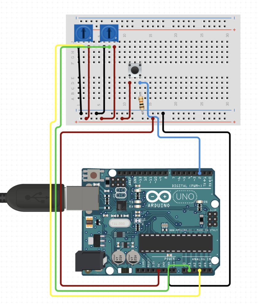
In the examples above we controlled LEDs from SuperCollider. Here, however, we are going to do the opposite: using a push button and potentiometer on Arduino to control sounds in SuperCollider.
In Arduino:
int push = 0;
int pot0 = 0;
int pot1 = 0;

void setup() {
  Serial.begin(9600);
  pinMode(2, INPUT); // our push button
  waitForSuperCollider();
}

// a monitor function waiting to 'handshake' with supercollider
void waitForSuperCollider() {
  while (Serial.available() <= 0) {
    // send an initial string. must match the number of values you want to send
    Serial.println("0,0,0");
    delay(300);
  }
}

void loop() {
  if (Serial.available() > 0) {

    // read from supercollider
    Serial.read();

    // our readings in arduino
    push = digitalRead(2);
    pot0 = analogRead(A1);
    delay(10); // delay in between analog reads for stability
    pot1 = analogRead(A2);

    // below will serial print an array of values
    Serial.print(push);
    Serial.print(","); // adding comma!
    Serial.print(pot0);
    Serial.print(","); // adding comma!
    Serial.println(pot1); // finally, break line!
  }
}
In SuperCollider:
// evaluate to find the name of your arduino
SerialPort.listDevices;
// see post window

// make sure serial monitor is not open in arduino IDE
// then open port
(
~port = SerialPort(
	"/dev/cu.usbmodem141101", // your arduino's name
	baudrate: 9600, // must match arduino rate
	crtscts: true
);
)

// a loop for reading from arduino
(
~routine = Routine {
	var byte, str, val;
	inf.do { |i|
		if(~port.read == Char.nl.asInteger, {
			str = "";
			while(
				{ byte = ~port.read; byte != Char.ret.asInteger },
				{ str = str ++ byte.asAscii }
			);
			val = str.split(Char.comma).asInteger;

			// our sound
			// triggered and controlled form arduino

			// push button = on/off sound
			// pot0 = freq
			// pot1 = amp

			if(val[0] == 1, {
			{ SinOsc.ar(
				val[1].linexp(0, 1023, 400, 1600), 0,
				val[2].linlin(0, 1023, -30, -16).dbamp
			) * Env.perc(0.01, 0.1).kr(2) }.play;
			});
		});
	};
}.play;
)

// this will kick off reading (handshaking with arduino)
~port.put(0);

// stop
~routine.stop; ~port.close;
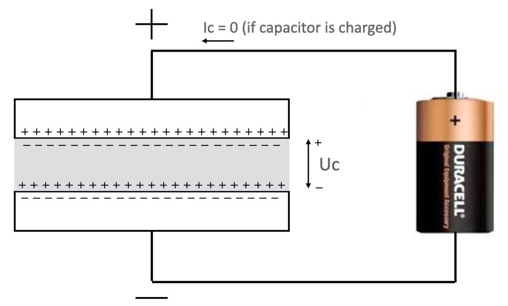
A capacitor is a passive component that consists of two metal (conducting) plates that are separated by a material called a dielectric. This dielectric is an electrical insulator that can be polarized by an applied electric field. The positive and negative particles inside the dielectric are not polarized if there’s no voltage applied.
The capacity of this component is measured in Fahrad. Common values in audio world are between 1pF – 10.000uF. When a DC voltage is applied to both sides of the capacitor, the capacitor will charge (look at the moved particles). For a very short time (time = 0) there will be a current flow that charges the capacitor. After the capacitor is charged, there will be no current anymore – until you change the polarity.
The capacitor is a super small chargeable battery.
Important to remember:
for DC voltages, the capacitor is a huge resistor or a blockade.
When an AC voltage is applied, the result will be different! Because of the changing direction of the current, the capacitor will be charged positive and charged negative and it will conduct the current in both ways. In other words: for ac-voltages (audio signals for example), the capacitor is a conductor. See the animation below.
When you want to make your own electronic device for the first time ever, you will encounter some challenges. How do you start? How can you make electronics stable and reliable. On this page some fundamental tips to help you create your own device.
Tip: Try to build the board or circuit ‘modular’. Do not build all parts of the circuit at once and on the end of the line connect the power, finding out it does not work. This can be very frustrating. Test your circuit while you are building. Build small sub-parts of the total circuit and test them separately.
Connect (or route) the power supply of the circuit first. Add functionality later. Try to use wire color consequently, especially for power connections: Red for plus power supply, black for ground, and blue for negativepower supply. This way it is easier to check for mistakes. If you do not have these colors available, try to stick labels to the wires.
Use the right cable for the right purpose: Thick(er) cable when the current is expected to be high (think of big speakers). Use shielded cable when the signal is very weak and/or high frequent. When you think the wire will move around (or vibrate), choose a cable that is flexible so it wont’ break.
Always build safe. Officially, by rule, any voltage above 48V is considered dangerous. When you are working with 230V~ AC, make sure no finger can touch /reach these voltages. Use good isolation and always be ‘aware’ of this lethal potential energy.
When touching 230V~AC, it’s the frequency in combination with the high voltage that’s dangerous. Our heartbeat is about 60 times per minute; one time per second. The frequency of the net is 50Hz; 50 times per second …
Building a Printed Circuit Board
Proto typing example
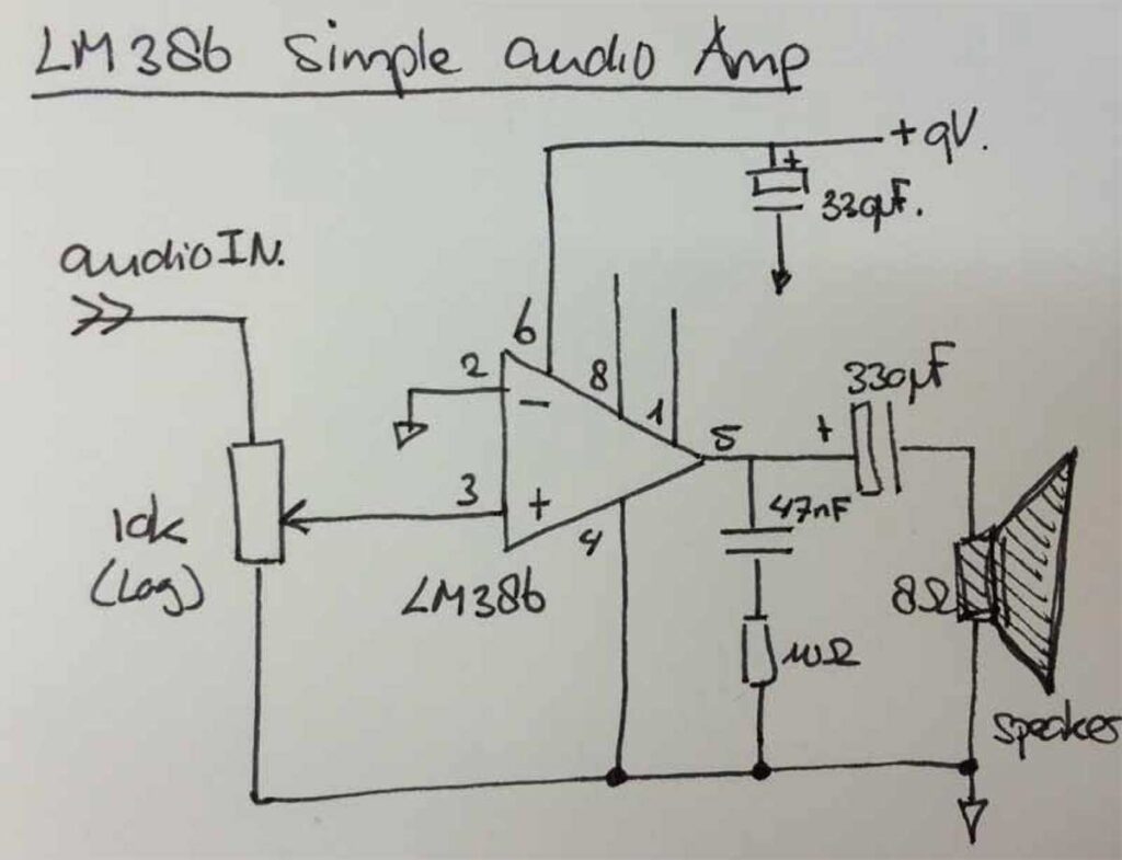
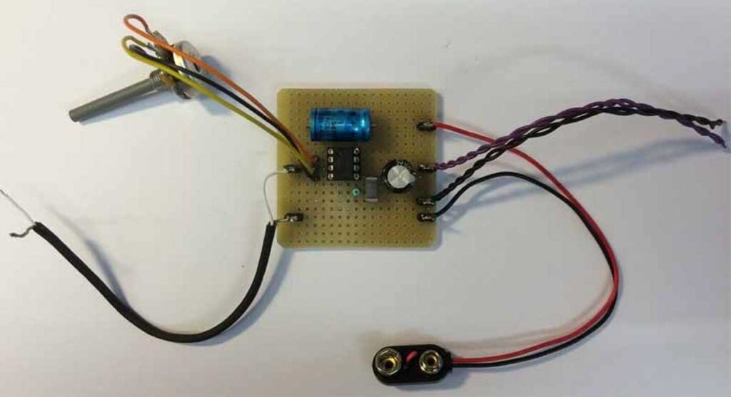
Below an example of how to transfer an experimental circuit (a simple audio amplifier) into a stable printed circuit board.
The circuit – LM386 audio amplifier, with an input volume potentiometer, an output filter, speaker and powered by a 9V battery.
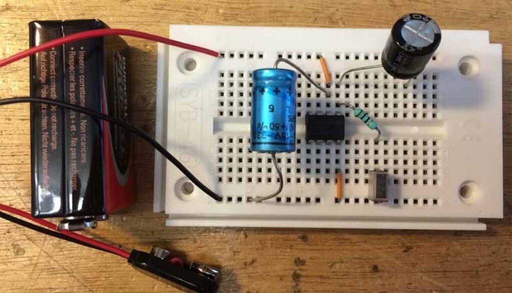
The circuit build and tested on a breadboard.
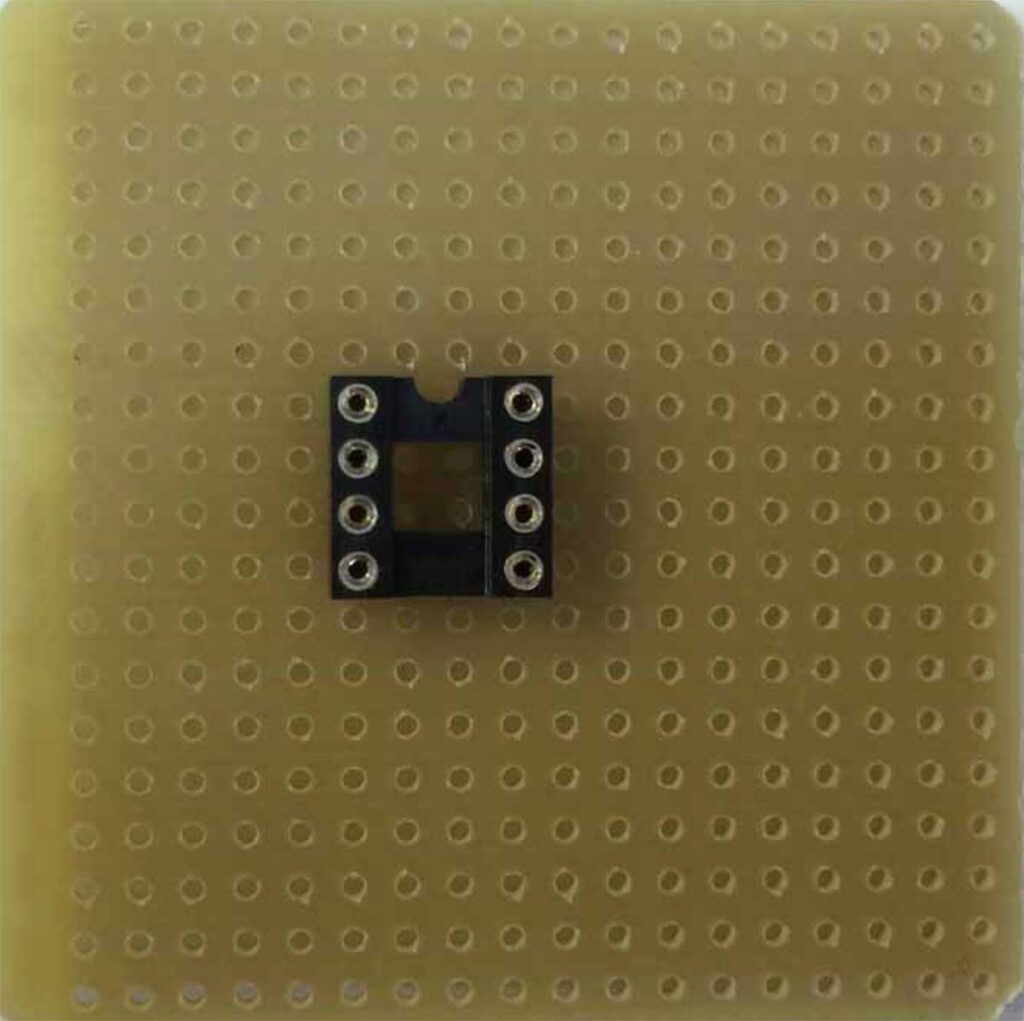
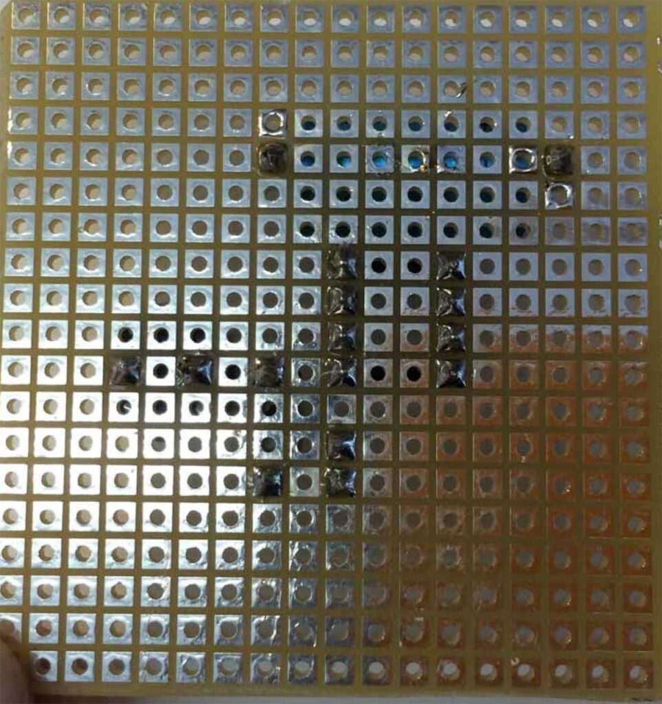
Place the component(s) on the right position. This side of the board is called the ‘component-side’.
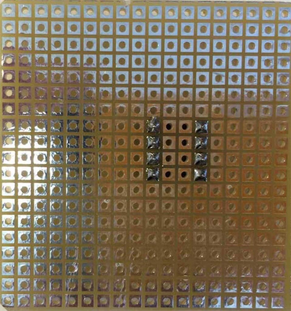
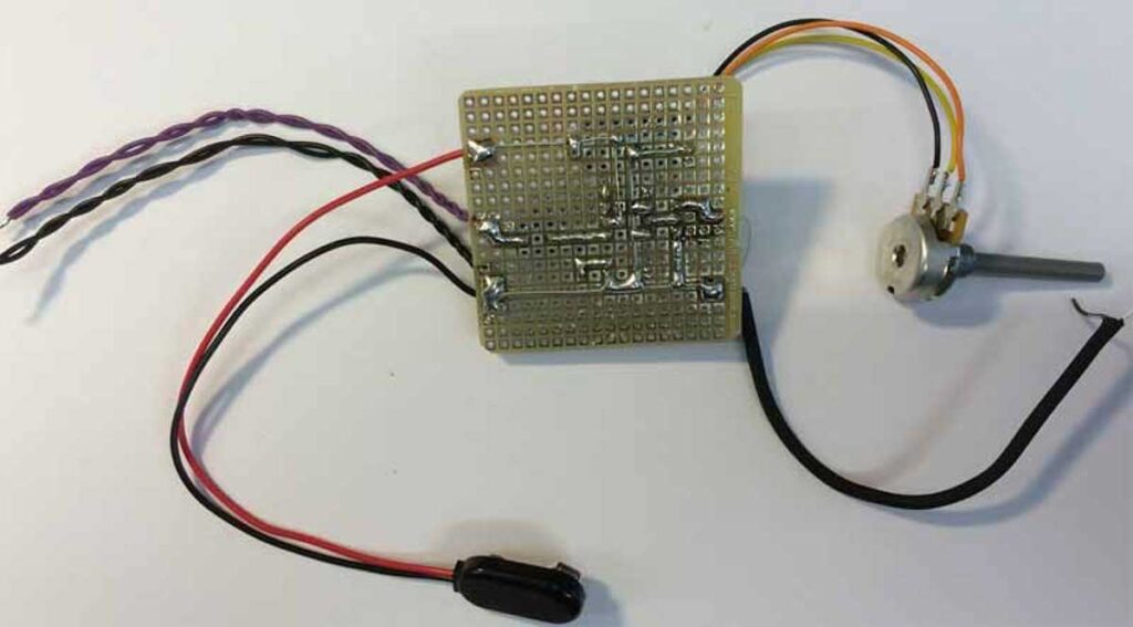
The other side is called the ‘soldering side’. This side has soldering pads, where the pins of the components are fixed (soldered).
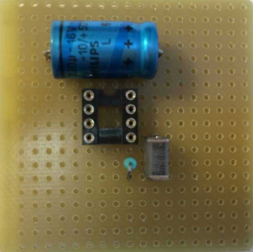
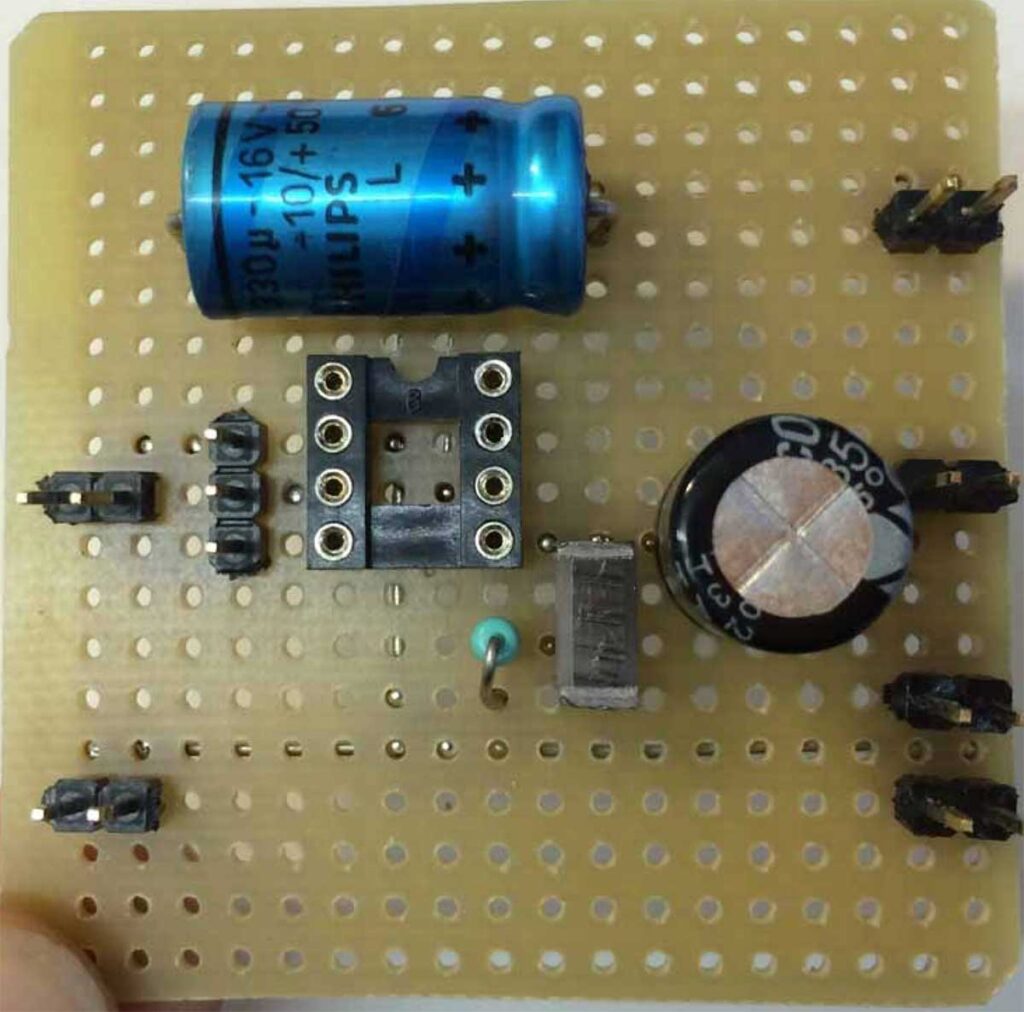
More components placed on the top-side – choose a practical location on the board, thinking ahead of how the connections below have to be routed.
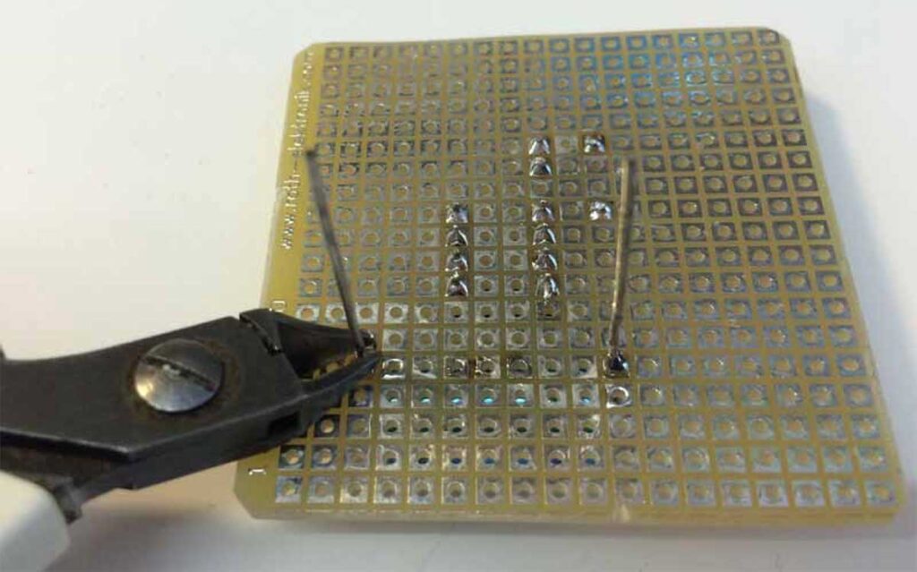
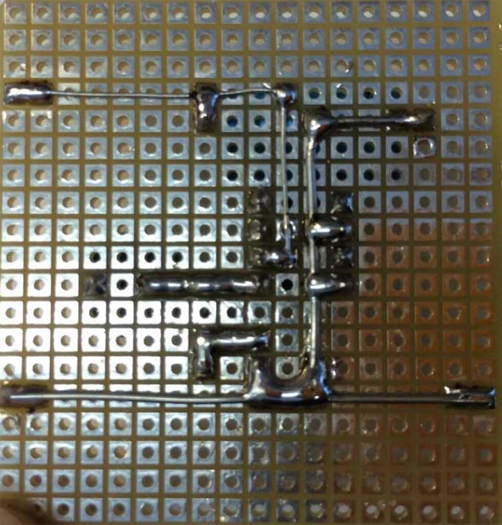
Cut the wires on the bottom side.
Be aware of the fact that the connections are ‘mirrored’ when compared to the top-side.
Connect the points with iron wire to realize the circuit. It’s a good idea to use thicker wire for the GND connections.
Place some ‘male-headers’ to have the possibility to connect the wires.
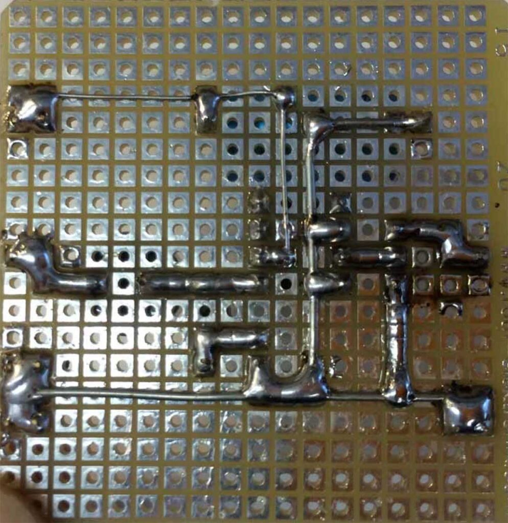
Make the connections complete on the bottom-side.
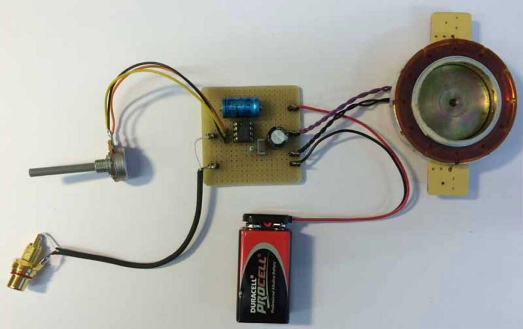
Connect the wires , the battery and the speaker,
The backside, or soldering side complete.
Finished!
How to connect ‘Ground’
When you connect power to a circuit, use thicker wire for the ground. The ground should always be very LOW IMPEDANT. This means, the resistance should be low. Thicker wire does the job …
Think of the water supply in your house: the water is entering your house through a tube of 14mm, but going out in a big tube. In other words: using thicker wire for the ground, avoids disturbances and unpredictable behavior. Also check how you connect the ground.
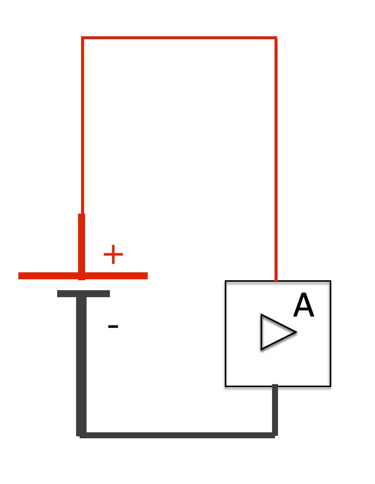
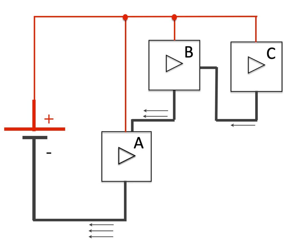
A simple setup of a circuit with “A” being a circuit or a component connected to the power.
Connecting a circuit like the example above can cause ‘noise’ problems. The ‘dirty’ ground from process C is polluting the ground of process A and B. Always make sure that the ground of a certain process (this can be an opamp, a motor or other electronics) has a separate ground connection …
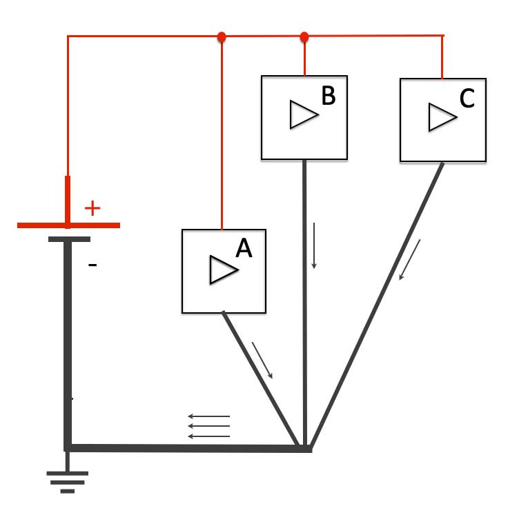
Always try to connect the ground into a star
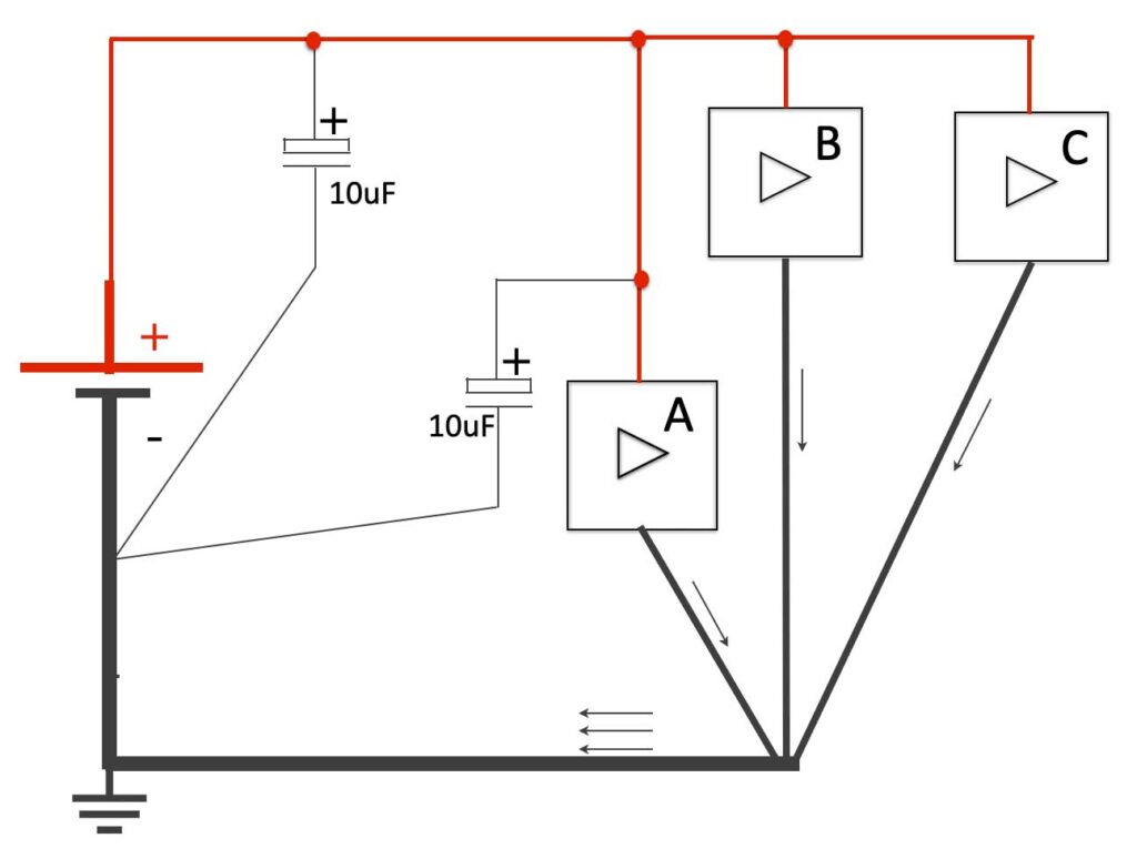
If connecting the power to a circuit, it’s a good idea to add a capacitor. This will function as a LowPass filter; it will take away disturbances.
Electronics is great and it is all about the control of currents and voltages in a circuit. By using the right components with the right value in the right order, the most fantastic applications can be created. Let’s start looking closer to the symbols that are used when we talk about components in a circuit.
Common symbols/components
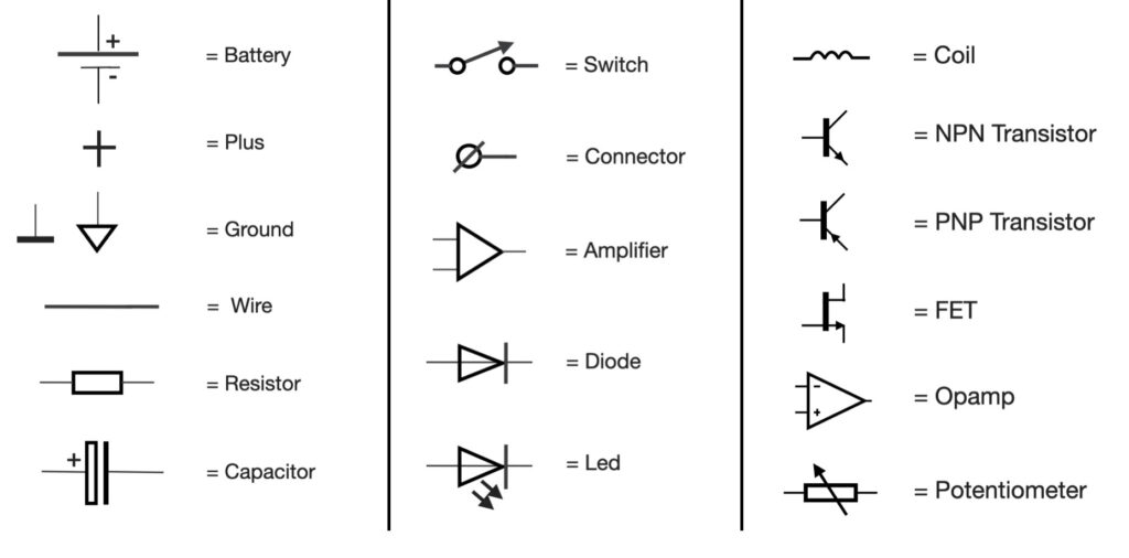
European symbols
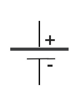
Starting with the generic symbol of a battery, or a DC-power supply. The “+” indicating the positive connection and the “-” the minus or zero. Often the zero is also referring to ‘ground’. This is the fundament of a circuit: the power supply.
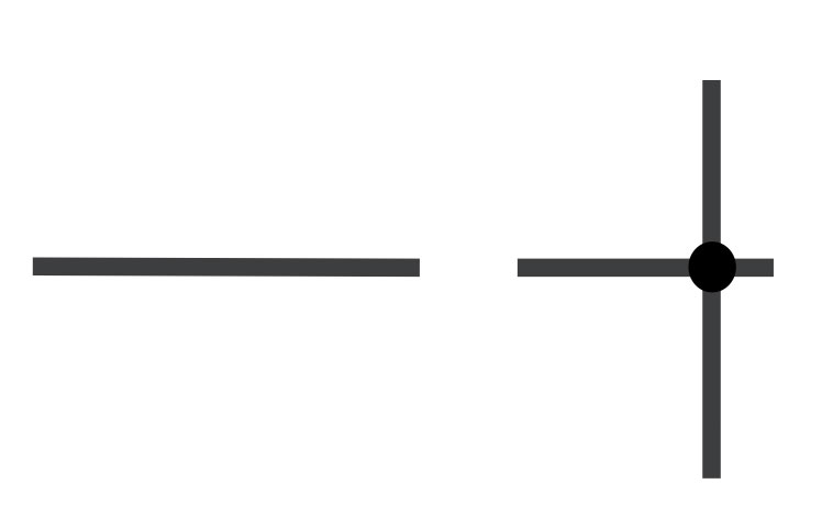
A line is referring to a wire which is a electrical connection between multiple points in a circuit. When two lines cross, a dot indicates a junction – there is a connection. When two lines in a circuit diagram cross without a junction – there is NO connection.
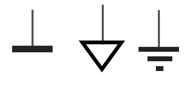
There are a lot of different symbols indicating ‘Zero’ or ‘Ground. The symbol with the 3 lines is indicating earth literally. A connection to the physical ground. Ground (zero) is a reference.
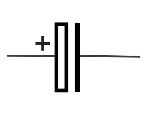
Capacitors are simple passive devices that can store an electrical charge on their plates when connected to a voltage source. Read more …
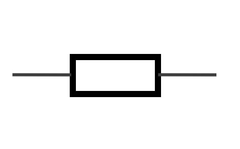
A resistor is a component indicating ‘resistance. The bigger the resistance, the smaller the current through the resistor. Resistors can have many differents packages. In general 1/8 watt resistors are used in audio circuits referred to in this website. The value of the resistor is indicated with colored rings. Check this link for the values.
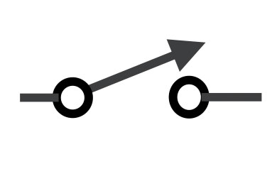
Switches can be found in lots of packages or configurations. A switch creates a connection (ON) or an infinite resistance (off).
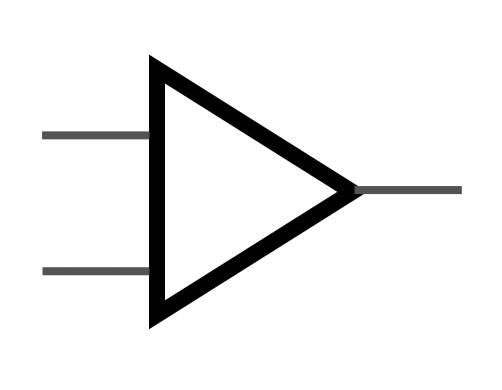
The common symbol for an amplifier is a triangle. It is not referring to specific type, but a general indication that a signal is ‘amplfied’.
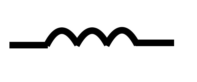
A coil is a a long wounded wire (around a core) creating resistance for higher frequencies. Therefor coils are mainly used in filters.
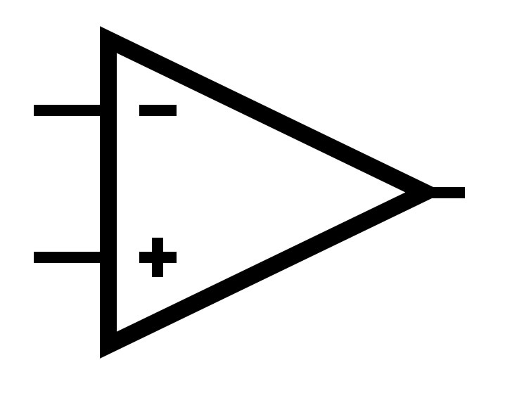
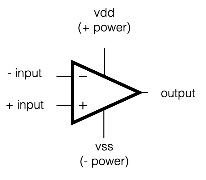
An Operational Amplifier, abbreviated opamp. This ideal electronic building block has an inverting and a non inverting input and one output. Check this page for more details.
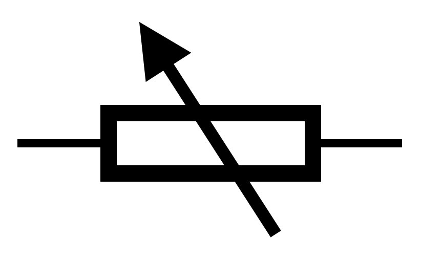
A potentiometer is a variable resistor.
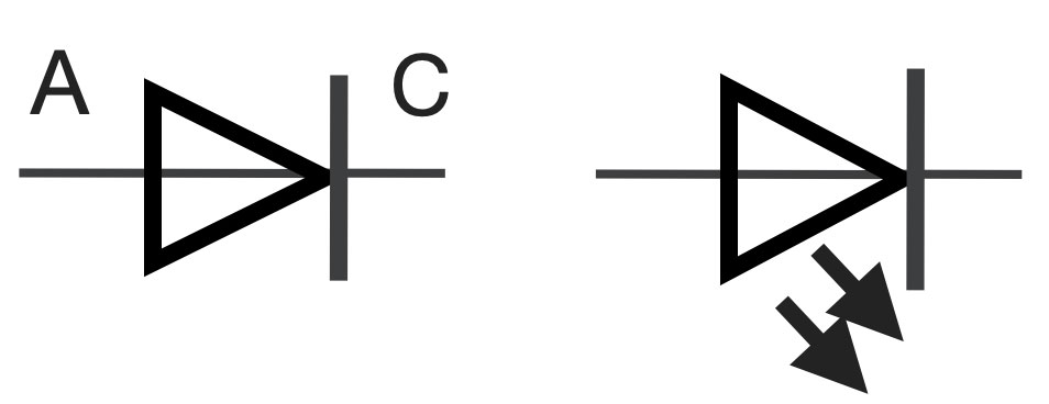
A diode conducts current in one way only – therefore its symbol looks like an arrow. The “A” indicates the Anode (positive) and the “C” the Cathode (negative). The diode with the two arrows indicate a Light Emitting Diode or LED.
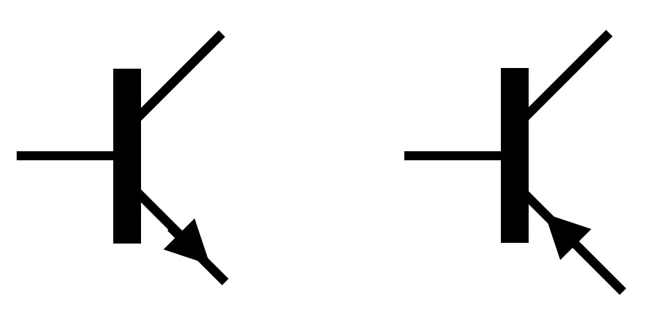
One of the most important components of ‘modern’ electronics is the transistor. The transistor exists in many different shapes. The most common ones are NPN and PNP. Check this short movie of the transistors for more details.
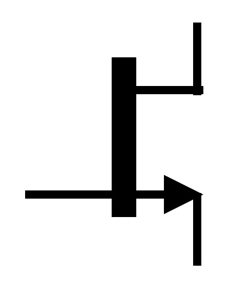
A Field Effect Transistor or FET. The bg difference between a transistor (BJT) and a FET is the way it is driven. a transistor is current driven and a FETis voltage driven.
While making all the projects, I’ve been using a lot of different Opamp circuits and actually the basic concept of the circuits used, is often the “same”. In this article I will point out the most important Opamp circuits used in combination with active sensors. These active sensors, like for example the acceleration sensor, produce a tiny DC-voltage change, which has to be amplified and tweaked.
Some fundamentals:
The word “Opamp” is an abbreviation of ‘Operational Amplifier’ and is an ideal building block in electronics. There are 3 fundamental properties:
1. It has a very high input impedance (resistance): so it doesn’t take any current into it’s input. 2. It has a very low output impedance; so it can deliver a relative strong output current. 3. The amplification (Au) is very, very high.
In the circuits below, the power supply of the Opamps is not drawn. If you make use of an opamp, you will always need a power supply to ‘feed’ the opamp. Most of the times, especially in audio world, the opamp needs a balanced power supply, meaning +voltage, ground and -voltage. When I work with sensors, I do use Opamps that also work with a single power supply (+voltage and ground). For example: LM358, TLC274, LM324. For more information about the opamp itself, checkout the wikipedia or equivalent websites.
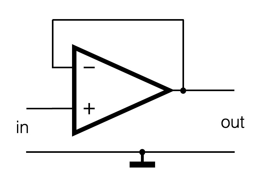
Follower or Buffer circuit:
This circuit is used to ‘buffer’ the output of a sensor. Often the sensor is placed far from the actual sensor interface, so long wires have to be connected to it. To avoid loss of the signal (the output of the sensor is not always capable of generating enough current), this circuit can be applied. The output of the sensor is connected to the positive input of the opamp. Because of the feedback from the output to the negative input, the Au (amplification) is 0dB, or 1x. The output signal is not amplified, but just ‘follows’ the input. The opamp is capable of driving more current and a somehow longer cable will not be a problem. The sensor just has to deliver it’s tiny current (almost zero!) to the input of the opamp.
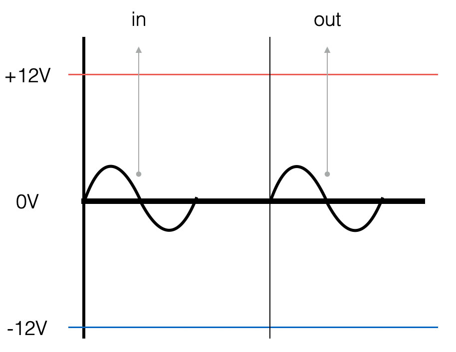
The graph on the right shows the input- and output signal of the follower-circuit. Both the amplitude and the phase of the signals are the same. Note the blue and red line. They represent the power supply lines which are connected to the opamp and thus representing the maximum Vtt (voltage top-top) the opamp can generate.
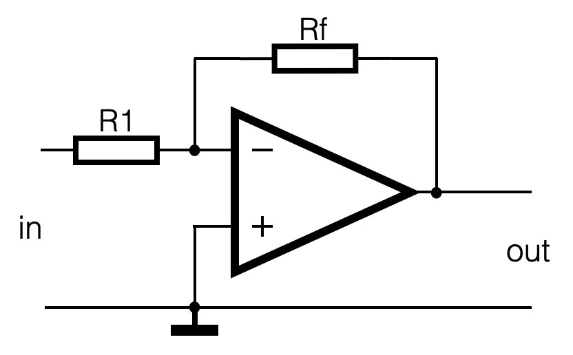
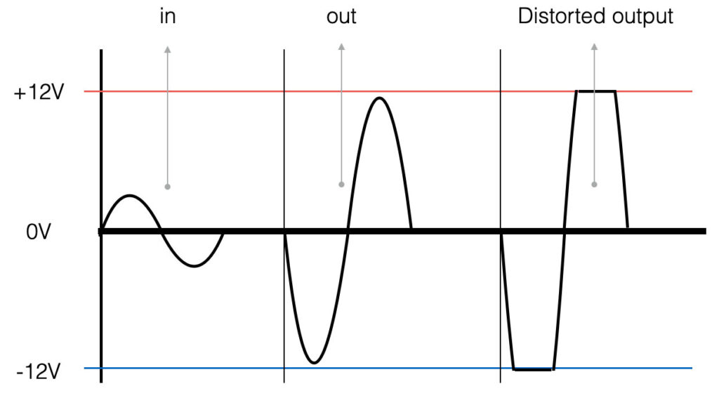
Non-inverting amplifier
The non inverting amplifier has an amplification which is always more than 1x (>0dB). The proportion between the both resistors Rf (R feedback) and R1 determines the amount of amplification. The output of the sensor is connected to the positive input of the opamp.
In formula: (Uout/Uin) = Au = (1+ Rf/R1)
The graph on the right shows the in- and output signal. The amplitude of the input signal is amplified. Note the distorted signal on the right! If the amplification (proportion of the both resistors) is higher than the maximum output swing of the opamp (Vtt), the signal will ‘clip’ and the shape of the signal will change (be distorted).
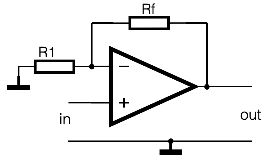
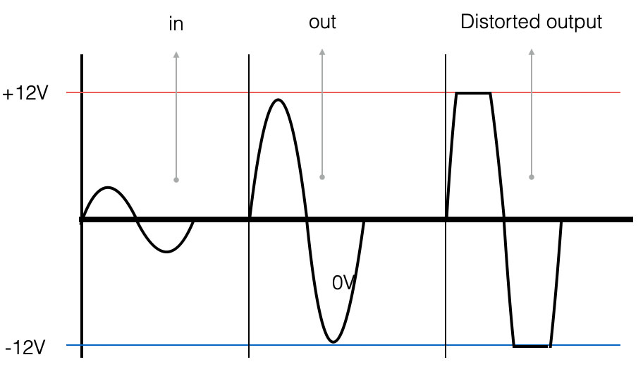
Inverting amplifier
The amplification (Au) with the inverting amplifier only depends of the proportion between Rf (R feedback) and R1. The output is 180 degrees out of phase with the input; it’s negative. This circuit is also known as the summation amplifier.
In formula: (Uout/Uin) = Au = – (Rf/R1)
The graph show the output signal inverted, it is 180degrees out of phase with its input. Also here, too much amplification can cause distortion.
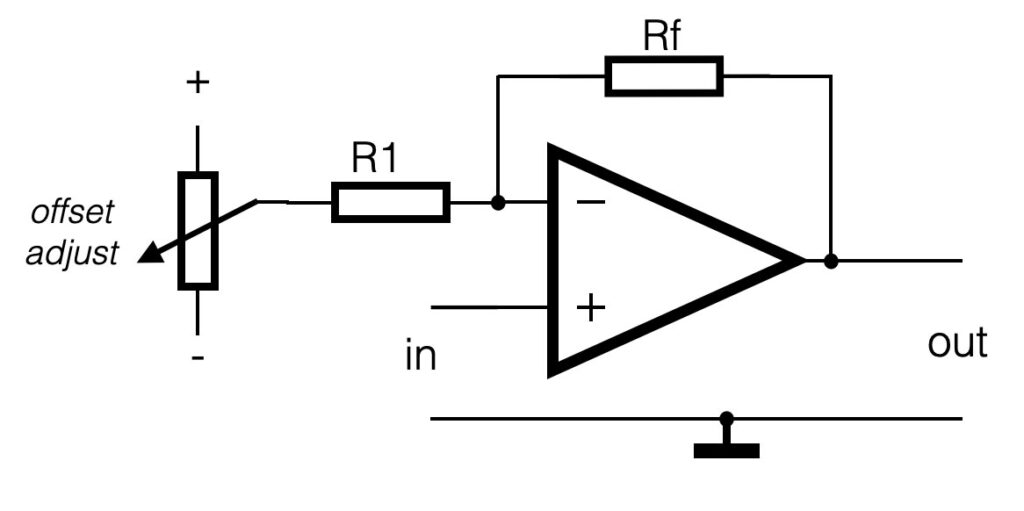
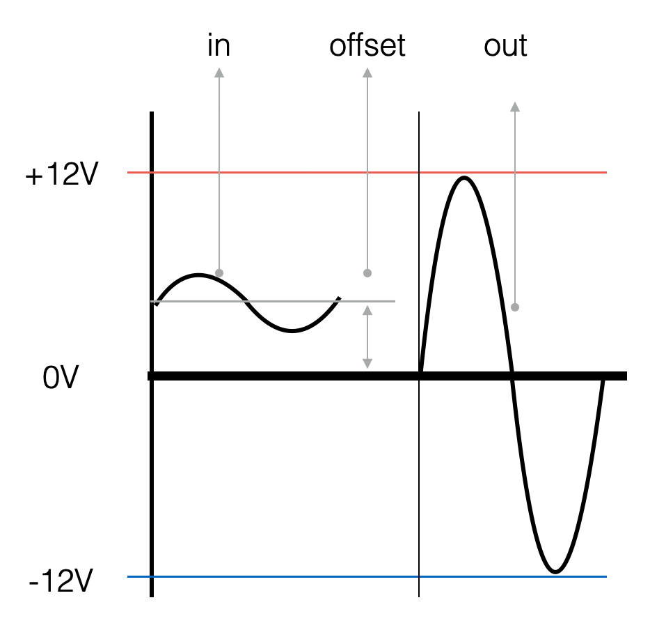
Non inverting amplifier with offset adjustment
A lot of sensors do generate a little DC-voltage change, but do have some DC-offset on the output. With the ADXL202 chip for example, the filtered output is “DC-change” (=AC) in reference to 2.5V. When the sensor is tilted to one side, the output will be 2V and tilted to the other side 3V. This means a maximum change of 1V. It would be better to have the output swing a big as possible – a higher resolution. In the circuit above, the amplification will be around 2,5 -3 times (around 10dB). With the potentiometer connected between the plus and minus power, the output DC-offset can be adjusted to zero.
In the picture on the right a graphical representation
Electronics is an absolute fascinating world with the possibility to create any circuit and any functionality that you would like. But bear in mind: electronics can be very complex and frustrating as well. Circuits that do not work. Components that smell funny or circuits which are unstable. How do you cope with that? Let’s start with the fundamentals of electronics:
Wiki definition: Electronics deals with electrical circuits that involve active electrical components such as transistors, diodes and integrated circuits, and associated passive interconnection technologies. The nonlinear behavior of active components and their ability to control electron flows makes amplification of weak signals possible and electronics is widely used in information processing, telecommunications, and signal processing
Electronics is about the control of current in a circuit. If the current somewhere in the circuit is too small, it is not stable or not reliable. If the current too high, the temperature will be too high. It has to be somewhere in the middle. These lessons will give you a complete introduction to Electronics. We will focus on the basics and fundamental circuits that are applied in music and art. We will talk about the common applied components, passive and active and also the small programmable computers (Arduino, Teensy), or sensor interfaces will be part of the subjects.
Electrical current
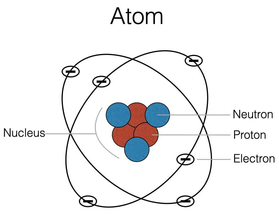
All materials you can imagine are made out of atoms. The core of an atom is the nucleus which has protons and neutrons. In the outer shells there are electrons. Check the picture below.
Materials that do not conduct current, like wood, glas or plastic do not have free electrons, because the nucleus with positive particles is in balance with the negative electrons. Materials like copper, gold or metal are not in balance. They have more electrons in the outer shells which are not linked to the positive nucleus – this means they are free to move through the material. We have free electrons and thus: conductance.
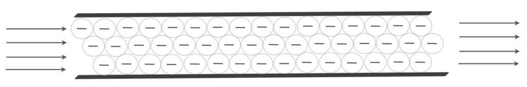
When you think about current through a wire, you can imagine electrons like marbles (or water), that are pushed through a pipe (see image below). Electrical current is measured in Amperes. If the current is one ampere (1A), it means that in one second 6,242*1018 electrons pass a given point. The more current flows through a wire, the thicker the wire should be. Check the video section of the webiste.
The amount of current (Ampere) through a wire is determined by the applied Voltage (V) to that wire and the amount of resistance (Ohm) of that wire. This brings us to Ohms law. See lesson 1
Kirchoff
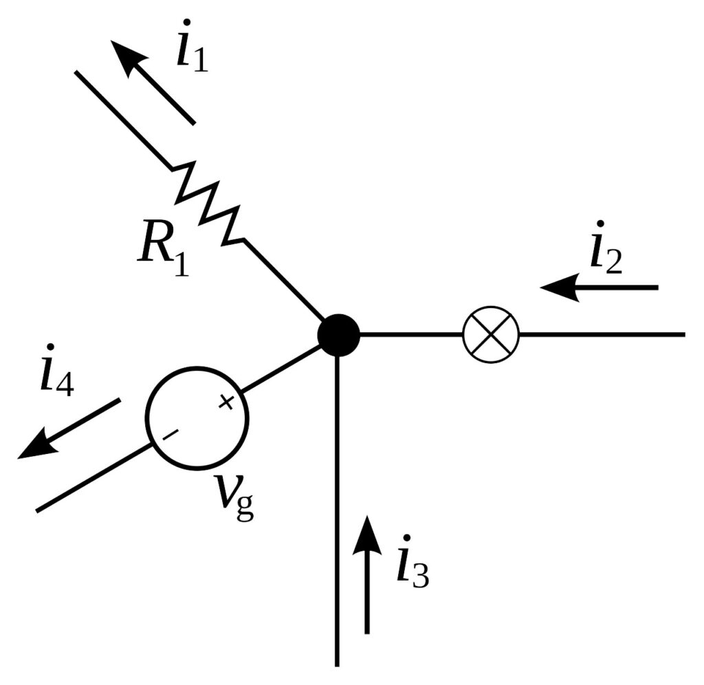
The behavior of current and voltage in a circuit is defined by the two laws of Kirchoff: Kirchoff’s first law:
For any node (junction) in an electrical circuit, the sum of currents flowing into that node is equal to the sum of currents flowing out of that node.
This means that the current entering any junction is equal to the current leaving that junction. In math: i2 + i3 = i1 + i4
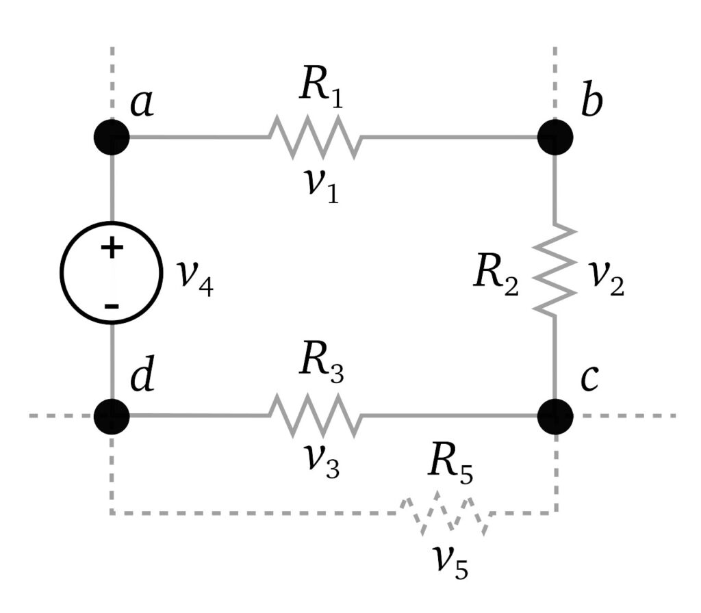
Kirchoffs’s second law:
The directed sum of the potential differences (voltages) around any closed loop is zero.
The sum of all the voltages around a loop is equal to zero. In other words: v1 + v2 + v3 +v4 = 0
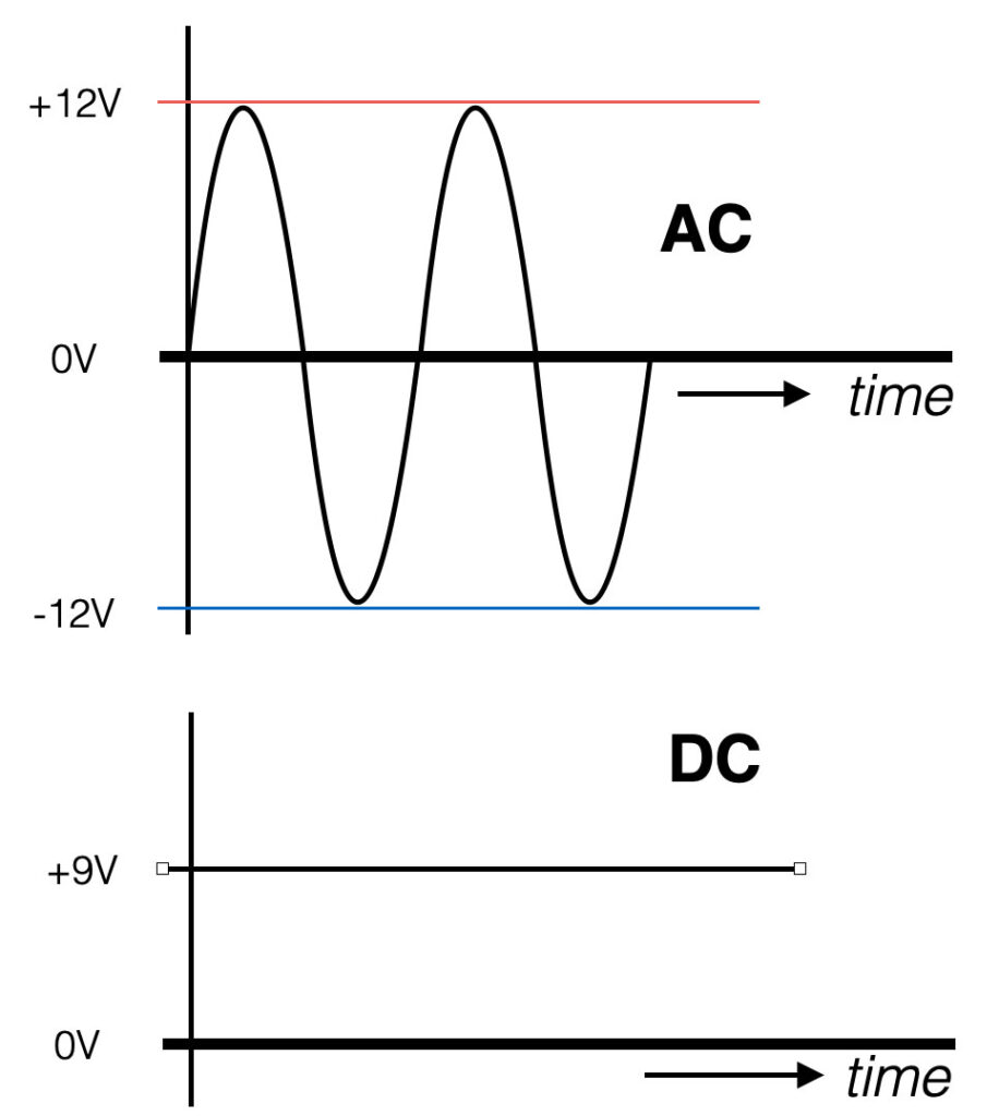
AC and DC
AC stands for Alternating Current. The value of the signal changes polarity over time with a certain frequency. The AC current will move both ways – back and forth.
DC stands for Direct Current. This means that the voltage does not change polarity over time. It is a straight line in the figure. Think about a battery. The plus (+) and minus (-) indicate you are dealing with DC. The current in the wire will move in one direction only.
Frequency
The frequency of a signal defines the amount of changes per second and is measured in units of Hertz [Hz]. So if we have an AC signal that changes (polarity) over time, this signal has a certain frequency.
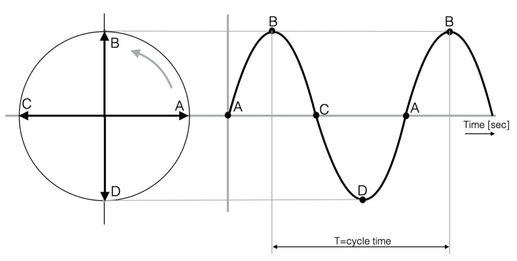
Looking at the figure below you see a representation of a sine-wave. The circle on the left represents a rotating point (think of the pedal of a bicycle) – with starting at point “A”. The point rotates left and will go up towards point “B”. If we would draw the position of the moving point in time, we will see the first 90 degrees of a sine-wave. Following the pedal from “C” to “D” and back to the beginning at point “A”, we see a full sine-wave (360 degrees). This one full circle is also called one cycle (T). The variable T indicates the cycle time in seconds.
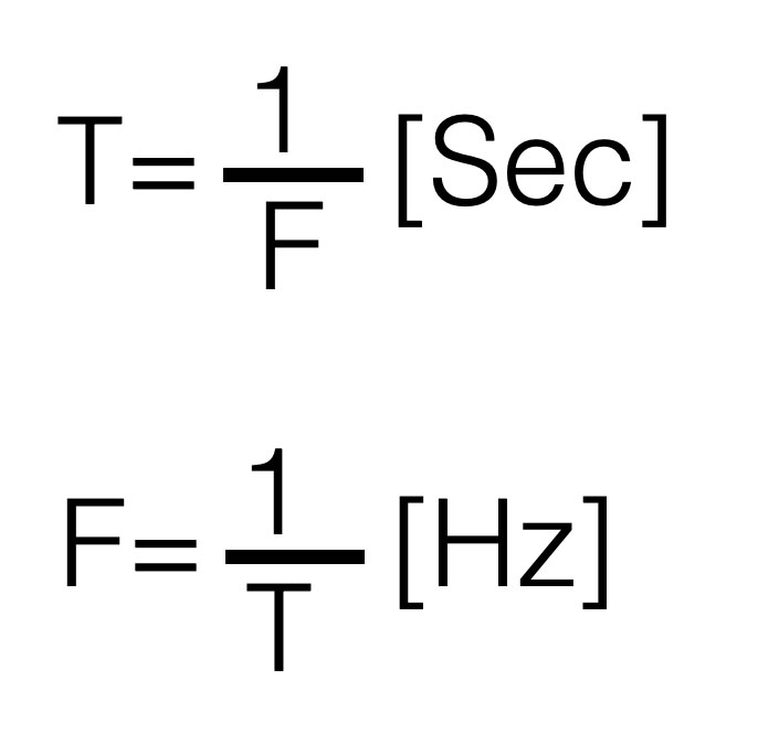
The amount of cycles that fit into one second (1 sec) is called the frequency F. So if we talk about a frequency of 1kHz (=1000Hz) this means that this signal makes 1000 cycles in one second.
Written in formula this looks like this. The smaller the cycle time , the higher the frequency.
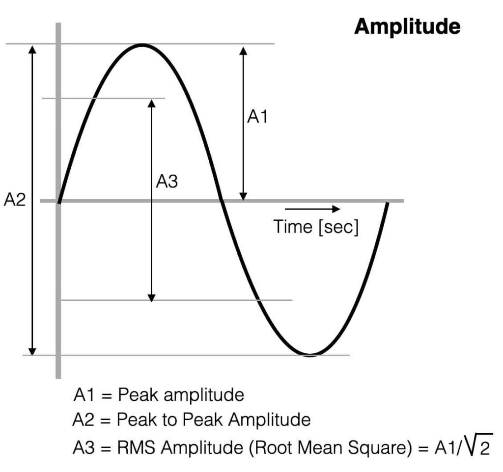
Amplitude
The Amplitude, often indicated with “A” is a value for the “strength” of a signal. The Peak to Peak Amplitude (A2 in the figure) is the change between the two ‘peaks’ of the sine-wave – the maximum swing.
If you want to measure the average value of the sine-wave, this is called the RMS value of the Amplitude. (A3) The multimeter shows the RMS-value.
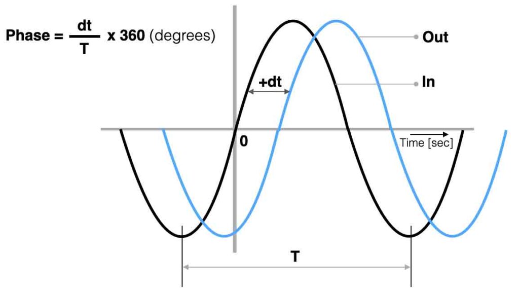
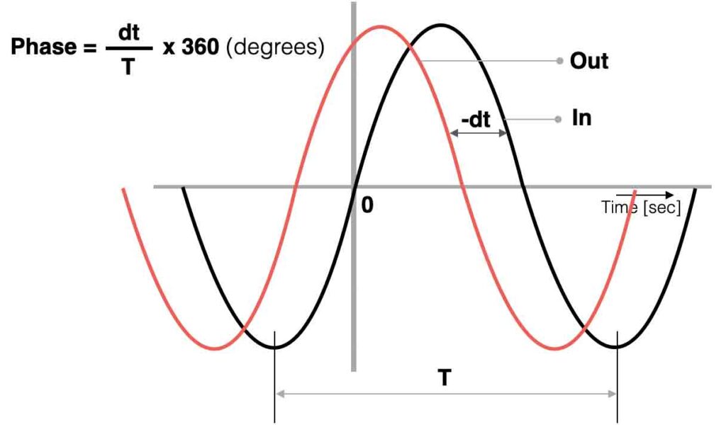
Phase
A mono signal cannot have ‘phase’, because phase is referring to a time difference between two repetitive signals. A sine-wave and a cosine-wave for example have a phase ‘angle’ of 90 degrees ( = 1/2π).
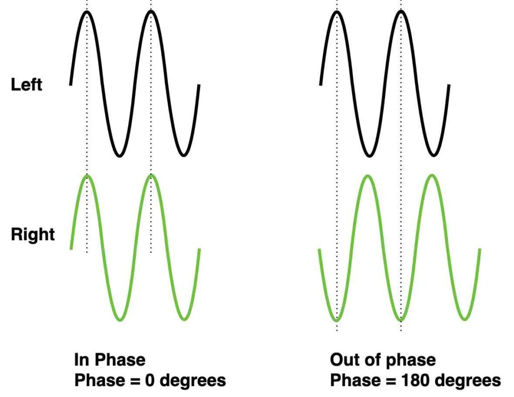
When two speakers are connected to an amplifier the correct way, both loudspeakers move forward and backward exactly the same time – the waves are ‘in phase’. If the connection of one speaker is then inverted (minus and plus swapped) we introduce two speakers that are ‘out of phase’. Check the waves below.
Electronic filters are created with time dependent components like capacitors or coils. When we connect an ac-signal (audio signal) to the input of a filter we can compare the in- and output to determine the ‘phase angle’ between both signals. In the figures below a positive- and negative phase example.