How does a basic RC filter work?
If we know that a capacitor act’s as a blockade (huge resistor) for DC ánd that the capacitor is a conductor (low resistance) for AC, we can make voltage ‘dividers’ that changes resistance and thus output voltage, at different frequencies.
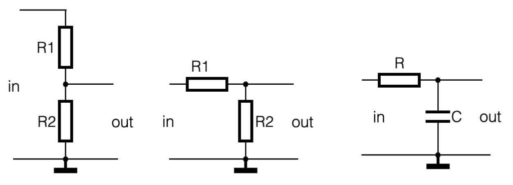
If we combine a resistor and a capacitor in a series connection (the voltage divider for example), the behavior of that circuit changes because a time-constant is introduced.
R x C = time constant [seconds]
Low Pass Filter (LPF)
Take a look at the figure below. If we connect DC on the input of this RC-circuit, the capacitor will act a ‘infinite’ big resistor. The output will be equal to the input. If we change the input to AC, the resistance of the capacitor will change – it becomes lower. This means, the amplitude of the output will go down as well.
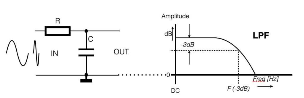
If we would give this filter a frequency ‘sweep’ (= change the frequency from low to high values), the voltage parallel to the capacitor (=output) will drop.
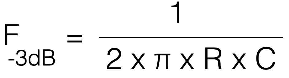
The frequency at which the output is half of the value of the input (this equals -3dB) is called the ‘cutoff frequency, F -3dB
High Pass Filter (HPF)
If we change the position of the R and the C in this simple circuit, the behavior will change as well. Take a look at the picture below.
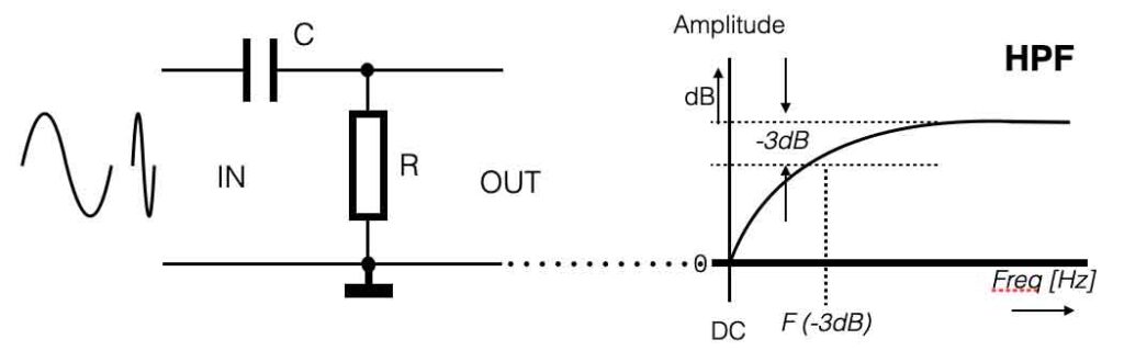
If we start with DC as an input voltage (frequency = 0Hz), the capacitor acts as a very high resistance again. The output will therefor be low. Adding a sweep from low to high frequency will increase the output value. We introduced a High Pass Filter.