Power supplies
Working with electronic-circuits means you are always in need of ‘power’. A lot of circuits work with battery operated power. This is not really dangerous and if the battery ‘dies’ on you, you just buy a new one. But for a lot of reasons (environmental, money, more power) it’s a better choice to make use of power-supplies.
A power-supply takes its energy from the wall-socket (in Europe 230V AC/50Hz / USA and Japan 110VAC/60Hz) and converts this into low voltage DC. So before we have a power-supply that provides us with (let’s say) +9VDC, there are some important steps to take.
Transformer
The first thing is to transform the 230V~ (Europe) down to (for example) 12V~. This is done by a transformer. A transformer is in its fundamental a piece of metal with two coils wound around it. See the picture (thanks Wiki). The red wire is the primary winding and the blue wire is the secondary winding.
The red wire is connected to the mains (230V~) and is inducing a magnetic Flux within the metal core (green dotted line). In the blue wire, wound around the same metal core, an electric current will flow (induced) because of this magnetic flux. If the amount of windings on the primary side (N1) is equal to the amount of windings of the secondary side (N2), the voltage on the input and output are equal. But let’s say the primary coil has 1000 windings and the secondary coil has 100 windings, the output voltage (the secondary voltage) will be 23V~ (230 * 1/10). So the proportion of the primary and secondary windings ( N1/N2) determine to which value the voltage is transformed. In practise there are values that vary from 6V~, 9V~, 12V~, 15V~, 18V~, 24V~, … Note that the output (~) is still an AC signal. It has a smaller amplitude but it still has the same frequency (50Hz).

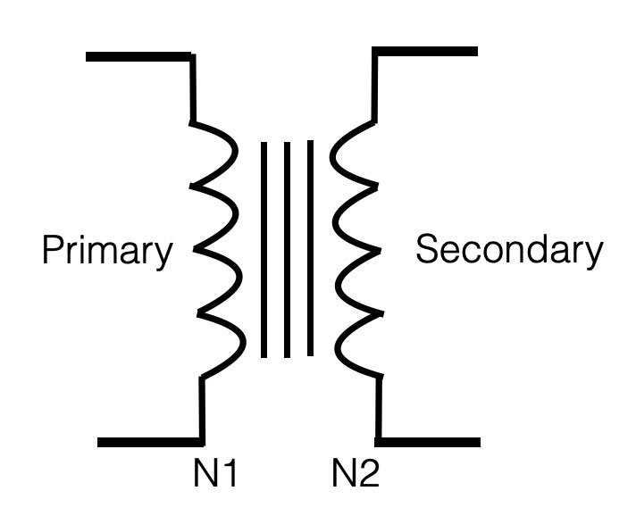
Important notice is that a transformer only works for AC!
Since the coil is just a long wire, it’s (dc) resistance is low and when a DC-voltage is applied, the current will be too high (the coil can burn). For AC-signals a coil acts as a resistor, so for AC the resulting (ac) current will be smaller.
The other reason why only alternating signals works for a transformer, is that we need alternating current to create a constant changing magnetic field (flux). Due to this changing magnetic filed, a current will be induced in the secondary coil.
Recitification
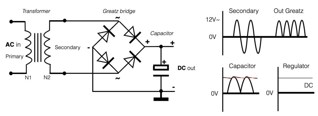
The next step in the design of a dc-power-supply is to ‘rectify’ this low secondary AC-output of the transformer and change it into a DC-signal. This is achieved with the use of 4 diodes actually placed into a bridge-circuit, also called Greatz circuit. These 4 diodes connected to an AC-signal will double rectify the AC-signal. If a big capacitor is placed parallel to the output of the diode-bridge, the rectified output will be smoothed and the ‘gaps’ between will be filled. See the figure below.
Voltage regulation
The setup above shows the very standard and simple power-supply setup. The DC output of this setup still has some ‘ripple’ (= dsiturbance) on top of the DC signal (see the ‘capacitor’ part of the graph). To make a ‘perfect’ straight DC output, we make use of so called regulators.
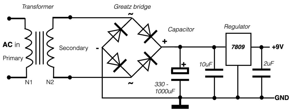
Regulators, like the ‘7809’ in the example above, do come in all kind of forms or shapes. The 78XX series are positive regulators and the number (XX) determines the value of the voltage they will regulate. Of course this is only possible if the voltage in the input is higher than the regulated output. In general the difference between the in- and the output should be at least 2,5V. The capacitors used on the in- and output of the regulator are here to avoid oscillation and they are placed as near the regulator as possible. The power supply with only +9V output is also called a ‘unbalanced’ power supply. It is only one value.
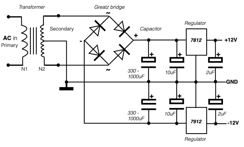
If you want to work with audio circuits you most likely need a balanced power supply. This is a supply that provides you with both plus and minus values. An example below:
Single sided power
“Unbalanced power supply“
When you are in need to power your circuit, most of the time you will use a battery (or a powersupply as decribed above). A single battery provides you with only (for example) +9V DC in relation to the 0V – hence the plus and the minus connection. Take a look at the picture below.
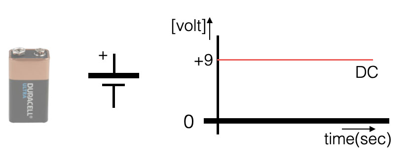
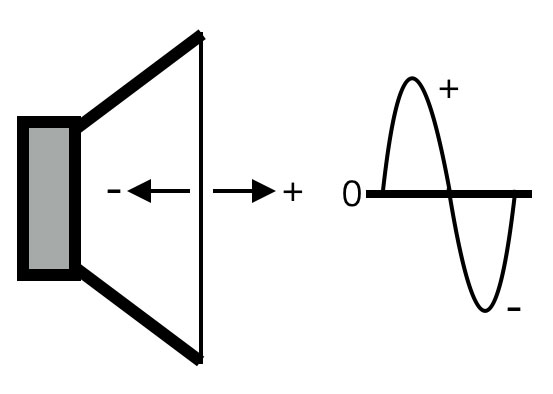
For a lot of circuits this single battery will be fine. It can provide the circuit with 9V and a small current of (more or less) 100mA. If you want to power an audio circuit (opamps for example) with only one battery, then you will encounter a challenge. An audio signal (AC) is positive AND negative! If you think about a speaker that generates sound, the membrane of the speaker will move forwards but also backward – through the zero (rest) point. See the picture below with a speaker moving forward (+) and backward (-).
A circuit that amplifies an audio signal needs to have ‘balanced power’. A single-sideded powersupply (like a battery) can not provide this- it is only positive. If you would connect an audio amplifier to a single sided powersupply, the picture below shows what will happen:
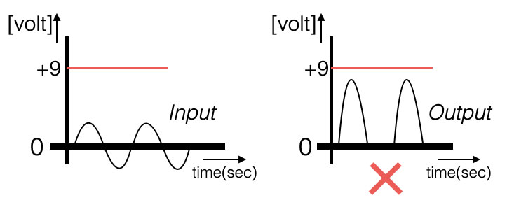
The negative part of the sinewave cannot be amplified, because there is no negative power! So how can we make sure that the negative part of the sinewave will be amplified as well? The answer: use a balanced power supply. This is a power supply with two sources, placed in series.
Double sided power supply
“Balanced power supply“
If we take two batteries (or voltage sources) and place them ‘in series’, we actually create 3 points. We have the plus, the zero and the minus. In general plus (+) is indicated with red, ground or zero with black and negative (minus) with blue.
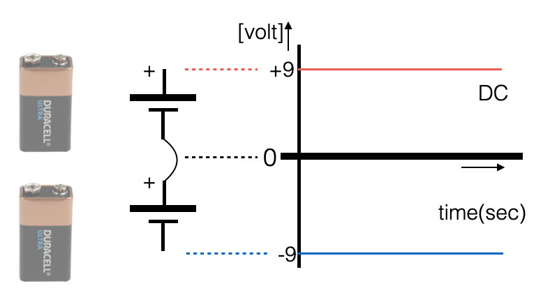
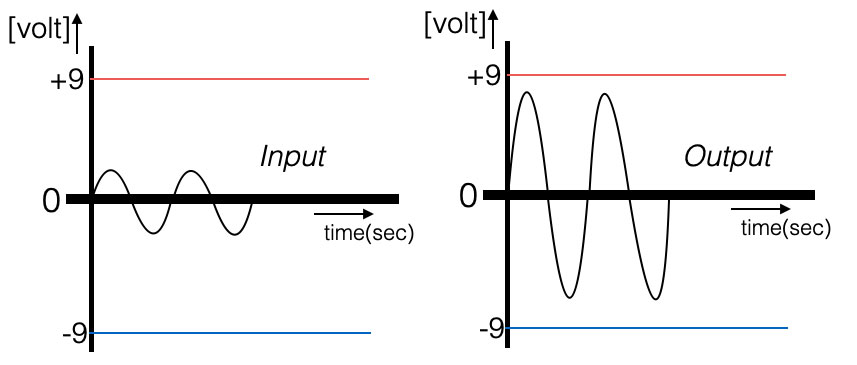
IF we now want to amplify a sinewave, we have positive AND negative power available and the audio signal can be streched up and down. See the graph below.
Create simple balanced power
There is also a possibility or ‘trick’ to avoid the use of two power sources or batteries. Like explained in the fundamentals and ‘Ohms law’, you can also create a voltage divider with two resistors. The two resistors divide the voltage in two equal parts, e.a. 9V divided by two creates two times 4,5V. See the image below:
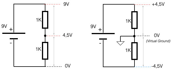
The middle point (0V) can now be used as ‘ vritual ground or ‘signal ground. In reference to that point you have +4,5V and -4,5V. We have balanced power. The signal-ground (virtual ground) should not be mistaken for the real ground. It still has a potential voltage of 4,5V. Circuits tat make use of this setup always have to apply a capacitor to get rid of the DC component.