This section introduces the serial protocol as a means to communicate with the Arduino by receiving messages from it, or by sending instructions to it. Its use here is explained from the perspective of using Max or Pd as interfaces. An examples of how to connect to Supercollider can be found here.
Examples on this page: led brightness • teensy midi • fading led • three motors
Arduino and basic Serial Communication
In order to establish communication with the Arduino, a serial protocol is used. This protocol is used for uploading instructions to the Arduino, but can also be part of an interaction scheme, for instance when sensor values need to be visualized in a user interface. The serial communication can be explained in its most basic form as a transport line of individual characters between the Arduino and a computer. It is possible to deviate from this basic form; that will be explained in another section in the future.
This section explains how to set up such basic communication between the Arduino board and the applications Max and Pd. Since these platforms are rather similar, patches for Max and Pd look somewhat identical. The Arduino can send data to Max or Pd, or it can receive data from it. In either case, data is represented by individual characters that are sent one at a time. Rather than the actual character, the transport line expects a numerical representation of that character. These representations are stored in a so called ASCII (pronounce: askey) table, which binds e.g. the letter ‘A’ to the value 65, or the character ‘7’ to the value 55. When sending data from Arduino, those ASCII representations remain obscure. All that is required is using the Serial.println command.
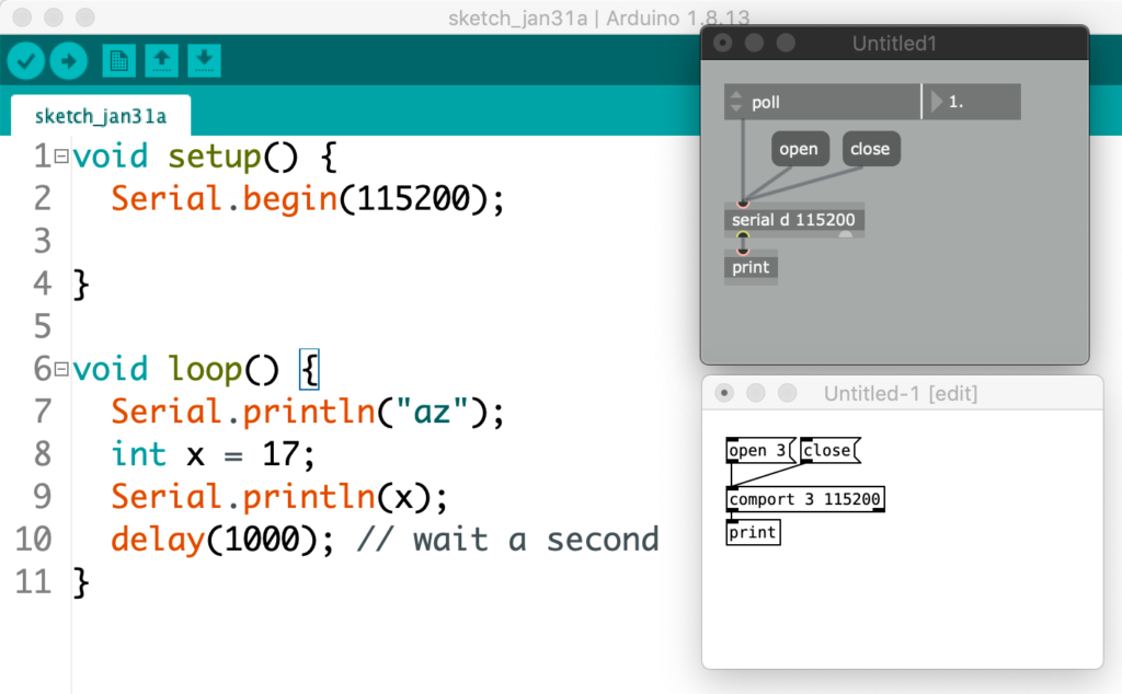
Serial.println("az");
int x = 17;
Serial.println(x);
The three lines above represents Arduino code that first sends the letters ‘a’ and ‘z’ over the serial port, and after that the value for x, which is 17, is sent. As said before, when sending, nothing shows that println uses ASCII representations. But at the receiving end, is will be ASCII that is received. The objects used are serial in Max and comport in Pd. The comport object is not vanilla and needs to be installed. Here is a how-to.
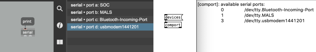
The connection to the serial port is created by providing a port reference. In Max this is a letter, and in Pd a number. With a specific message the information on available ports and their references can be printed. Arduino’s serial port is typically listed as ‘usbmodem’. The next step is to provide this identifier as argument, as well as the speed at which the communication is set up. The patches below show just this. The Max object that reads ‘poll’ is an attrui and is the easiest way to get data from serial.
The numbers that are printed out are in order: 97, 122, 13, 10, 49, 55, 13 and 10. After one second the exact same sequence appears. These values represent characters according to the before mentioned ASCII table. According to this table, the values 97 and 122 represent the characters ‘a’ and ‘z’, the values 49 and 55 the characters ‘1’ and ‘7’—indeed, numerical values are sent as individual characters. It is easy to see how this accords with the messages sent from the Arduino code. Twice, a combination of 13 and 10 appears. The ASCI table names these values ‘line feed’ (LF) and ‘carriage return’ (CR) respectively—terminology that suggests printer activity. These two values are inherent to the Arduino ‘println’ command and can be used in our patches as indicators that a complete message has been received.
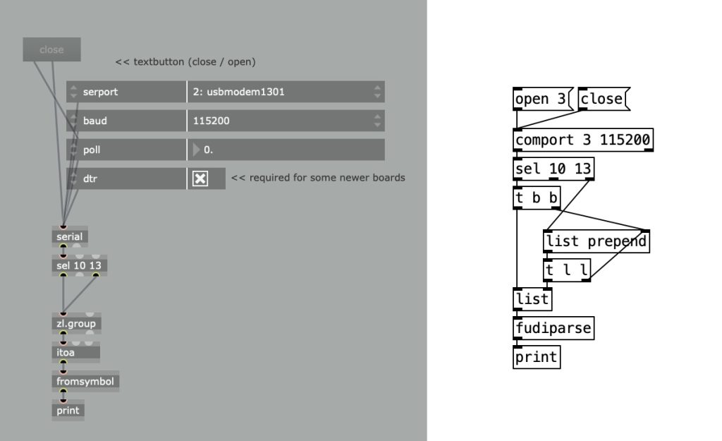
Max and Pd can transform the ascii values to the characters they represent using respectively the atoi and fudiparse object. Copy the code below into a Max patcher window to create the patch above.
----------begin_max5_patcher----------
609.3ocwWF0biBBDG+Y8SgCO6kAQiwzuJc5zAS3xQGEbPrM85zu6GrDS8tSq
NNLIODMrA3O+XWV17QX.pTdl0hhdH5wnffOBCB.SVCAWZGfpomOTQagtgDr2
jkufhc+jlcVClaTbgt2pnqlKpXZXDIWL1P0G9EWb5YE6f1oXQ1FbbTJAdQ1Y
elTrAG8zWyirS2OQ3KV4GAEMqhejPPVaeFFZeDuPDnZspiitttTzZllodlIn
kUrgRMJH1gCyyQy6ogaeNvSJY3qooqe1clzu2vbSCBcc.C.OaMbacVkcZsTr
Z1GgybL38.eXVA7c7.JuFgbnR1xPixd5f9ZVb.jMrqqxZ4Q12uEE69XCAGa2
hfumgIMxpp4iSvtst7LuFmjr6dRdIs63rj6RB3cvyumf2xTMRkdV1ub1w2ru
cMrOQhctVRGMud5b40I6.FyvqEtoNNu2i38Skrt885RY0Ju7BC3sM2qdvBOR
3uq1bRI6ZFkOxrNwsvEWYIyvG4ayMOZRYOxXKqxjA0bK6JiTwtaulyIlNEjk
TwIKn8uGE3cdEXEmtxP1jBrKxcstTnRuox8LDRnCnJt3eKwDVaV6+M4sxN0g
dUbmChi9Z4cj0p4Bpl6pQ3wq0.BcZzM2kJjoBAydwbJ4AgLWHu.j7gP42Jg1
dqDZA5ryC5jci3Y+BzovC5rjHNhmzgbCzANqNqCxGQBjEHz9+SGWVOZSyqLU
6kNCRXxr+hDJPrHFZxEtl4PSE6Ude+gj3HpxjAWaRe2ofkE5bdFxMTyeIRIL
kpZ6anENijvsFBSIqsMTGGvkKgeF9GvJeZp5
-----------end_max5_patcher-----------
Important to take into account is that only a single application at a time can connect with the Arduino board over the serial connection. In order to allow one application to open the connection, another must close it.
Telling apart multiple sensor values
When reading out multiple sensor values in Max or Pd, another approach than simply using println() must be adopted. In order to know which value represents the first sensor and which the second, the values are better send in such a way that they create a list. In Max/Pd a list can be specified as values separated by a space. The Arduino code shows how to create the spacing. Only after the last value has been sent, a println() is used to create a flag for the receiving end.
void setup() {
  Serial.begin(115200);
}

void loop() {
  int sensorValueOne = analogRead(A0);
  int sensorValueTwo = analogRead(A1);
  Serial.print(sensorValueOne);
  Serial.print(" ");
  Serial.print(sensorValueTwo);
  Serial.println();
  delay(10);
}
Example: set the brightness of an LED
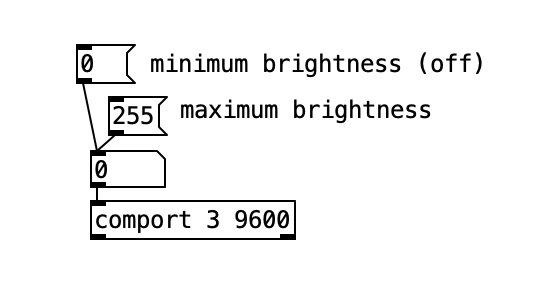
The section above explains how Max or Pd receive values from the Arduino. Communication in the other directions is possible too; from Max/Pd to Arduino. The dimmer example shows how this communication can be used to adjust the brightness of an LED by sending a changing value in the range from 0 to 255. This value is used to change the setting of a PWM value. Not much coding is Max/Pd is required to achieve this, simply connect a number box to the serial/comport object. The Arduino example even includes Max code that can directly be pasted into an empty patcher window.
Example: using a Teensy as a MIDI controller
The MIDI data that can be transmitted between musical controllers and computers, is essentially a variation on the serial protocol. The Teensy development board—which is like an Arduino–can easily be turned into a class compliant MIDI device, which means that it can function as a MIDI interface without having to install drivers.
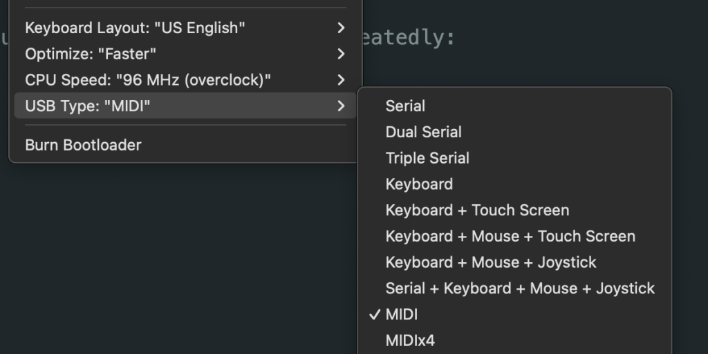
From the Arduino IDE, through the ‘Tools’ menu, the ‘USB Type’ can be set to MIDI. With the next upload, the Teensy will turn into a MIDI device and will be recognized as such by applications like Max, PureData or SuperCollider.
The code below extends the blink example so that it sends a MIDI note.
pinMode(LED_BUILTIN, OUTPUT);
}
void loop() {
usbMIDI.sendNoteOn(60, 127, 1);
digitalWrite(LED_BUILTIN, HIGH);
delay(1000);
usbMIDI.sendNoteOff(60, 0, 1);
digitalWrite(LED_BUILTIN, LOW);
delay(1000);
}
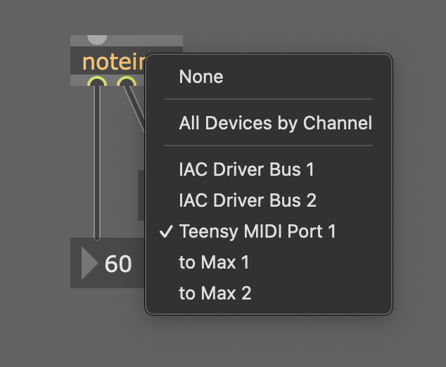
After uploading this code, Max will see the Teensy as a MIDI input, and pass the values as expected.
Example: fading an LED with potmeter
The fade example automatically fades the brightness of an LED between minimum and maximum. Closer examination reveals that although the pwm values used to fade are linearly increasing and decreasing, the change of light intensity appears not to be linear at all. If the left image below shows the linear change of pwm, the right image represents what the light intensity actually looks like; jumping rather quickly to high intensity and then slowing down while it reaches maximum value.

If linear intensity change is desired, it would be better to adjust the pwm values. Max provides a fine environment to prototype this. An audio rate oscillator provides the source of values. A potentiometer connected to A0, can provide a value for the speed of this oscillator. The patch below is an example of how to connect everything together. By raising the oscillator value to the power of three, we achieve a change of brightness that appears to linear.
----------begin_max5_patcher----------
893.3ocwX00bhCBE8Y8WASl8g1csNAxmtOs+OZ6zAUToSRfgfs11o829RfjV
6VbCpn8EQthb3buWtbfWFNHXJaCoN.7av0fACdY3fAZSMFFz1ePPIdyrBbsd
XAUjGYSuOXj4mjjMRs4YqvUKIcloy0FUC7pnjNiUqKoUEDoddfeXjsV1YMp0
JGKmshVs7NAYlzr5fg4iCGARP5l3vlOgpuCts8+XlF4Sbh4ODDLBDPqjcMfa
aF2qCG17wniisjMbAPMoWfRR9Im83E+XA7laFEc4uBGmboEu.Zxd3Ef86EBi
07OB5favmDutByqWwjuARrwxbqrDcfrLNWGkSlzOIWTvv9MDKTXP3pAABswz
r8fondYZTTplootkU6UhJET0V2Bxa.UtK3OEL6DNwug1XcBbdV+DtltrBW3U
JyWgqYh2rQyX+RSTno4aglkR1BabD5oZQlXXTttAkclKE8bIlCBUdZTD3pzP
vVwtsHKzdg2jCkro5.5jjSEYmSUIAVnw6UV4XAtjHIh6HU3oEZzBa+sZ5y59
JeRyp0iG3fx25X2lOOIkhahsSWKkrpupunfUaSdAJzEGiUePybqPROSbx6PV
xlSNHEJ4sYHlitzdsvdqjeLhSvRoXM0V1R1A6TrmXzfjoxIqnH3+jsXp201f
RiOUaS1M0SOUTeJd879o9jzuMlmbpXdMQvYBY+jOCchI+NNJfJYXKdD6k9iN
zRfeT7qOx46qarPvJqepbJy1QC4d8lEsAOmTh50SyKFuTI4laqDuWkZiflBz
vuAo10jB0xPcsMKrLaORV6+ZxPyUmhcHLNUo9ugocsdlwhcHnYOxZ6OnBM4q
QNt27KrTO7fBZ0+9VHZHar+YpWyVKl0MicuxA3CTmSpkzJrjZzWb86bdqwTR
myYpUSKhPX13D0FujsRO+TGHxTV0LNcucDobcQ27nD8tn6X1wgTtCH0sbNNj
bIPzsbNNjxbAoXegDrujKe38fNEmx7ARtj6gf9v6E6BRdIKGdtxHbILA8RRt
C.4kssgtvHej30LGn9hQdBmvy.NtrOJ2WQHnamvcbUFxb+nziCnzyEPImKfb
.mutGxH9Ay4OPD0sCVCgRg28L8U.yGo6RqLc0udVff7.sa7ZEoAXgRelTINa
sPurB1jZdSN8ipHpT2asQj2vFxofTqdrRcU0ZN1vCsHyguN7uveNS3B
-----------end_max5_patcher-----------
Example: adjust the speed of three motors
Adjusting the brightness of an LED, as explained above, can be turned into adjusting the speed of a motor. But in order to extend this model to multiple motors, another approach needs to be taken. What we need to solve is how to connect multiple number boxes to equally as many PWM driven outputs.
The solution lies in creating a separate function for dealing with incoming serial data with serialEvent(). The Serial Event example demonstrates the use of this function. A Max or Pd patch now sends various values separated by spaces, using an ascii representation. In this representation the space and return values function as flags that trigger the pushing of values into an array and updating the values to be written to the outputs.
int motorPins[] = {9, 10, 11}; // pwm pins
int motorCount = 3;
byte motorSpeeds[3]; // reserve space for three bytes
int motorIndex = 0;
String inputString = "";
bool dataComplete = false;

void setup() {
  Serial.begin(115200);
  // declare all pins as outputs:
  for (int i=0; i<motorCount; i+=1) {
    pinMode(motorPins[i], OUTPUT);
  }
  inputString.reserve(3);
}

void loop() {
  if (dataComplete) {
    for (int i=0; i<motorCount; i+=1) {
      analogWrite(motorPins[i], motorSpeeds[i]);
    }
    dataComplete = false;
  }
}

void serialEvent() {
  while (Serial.available()) {
    char inChar = Serial.read();
    switch (inChar) {
      case 32: // space
        motorSpeeds[motorIndex] = inputString.toInt();
        motorIndex += 1; // increase index
        inputString = ""; // reset string
        break;
      case 13: // new line
        motorSpeeds[motorIndex] = inputString.toInt();
        dataComplete = true;
        motorIndex = 0; // reset index
        inputString = ""; // reset string
        break;
      default:
        inputString += inChar; // add character to string
    }
  }
}
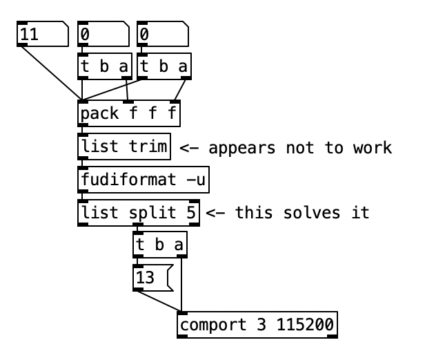
The Pd patch below works with the above code. However, the fudiformat object generates additional data to the extent that a list selector is included in the ascii values. Although the ‘list trim’ object promises to strip off this selector, that appears not to work. In order to solve this issue, an object ‘list split 5’ is added.
Useful Links
Using Timers
Multitasking
Debounced Encoder
…
