Oscillator principle

Oscillators with CMOS HEF 40106

An oscillator is an electronic circuit, that produces a repetitive electronic signal.
During this last lesson we will experiment with some some simple oscillators. Take a look at the animation on the right. This shows the resonance of a spring/mass combination, in an ‘undamped’ setup; so no losses due to friction. An electronic oscillator is more or less the same. A resistor (R) in combination with a capacitor (C) will also resonate. If we connect the R and the C to an active component (giving it energy to resonate), we have an oscillator.

Let’s take a look at the active component that we are going to use: a CMOS invertor, the HEF40106. This is an Integrated Circuit (IC) with six inverters in one package. The 40106 is also called a Schmitt-trigger, because of it’s hysteresis between the in-and output.


Principe

The circuit above shows the simplest setup of an oscillator. How does that work? Pin 2 (the output of the inverter port) is connected to the input of the same port through a resistor R. The input is also connected to a capacitor.

How does that work?
– Suppose the input at pin 1 is 0V (in case of start-up for example), the output will be ‘high’. If the power-supply of the chip is (say) 9V, the output is also 9V.
– At that moment the voltage at pin 2 is higher than pin 1, the current will flow through the resistor R, into the capacitor C.
–  The value of the voltage parallel to the capacitor will ‘slowly’ rise above the upper threshold and the output of the invertor will switch from 9V to 0V. Now the capacitor will discharge through the resistor, until the value of the input (pin 1) will drop below the lower threshold – the output goes ‘high’ again (it will be 9V).
– We are back at the beginning and the cycle will keep on going. It will resonate its own static frequency. The frequency depends on the value of the capacitor and the resistor. They determine the ‘speed’ of the proces.  The bigger the capacitor and the resistor are, the slower the system resonates, the lower frequency will be


Variations

Based on the principe explained above, there are lots of variations on the same theme. The circuit below has diodes in the feedback part, which will create different pulse width’s.


Master and Slave

The circuit shown is called a master-slave combination. The ‘ slave’ is only active when the output of the  ‘master’ is ‘high’, due to the diode. The capacitor and the resistor of the master have higher values and will resonate on a lower frequency. The ‘slave’ has smaller values and is oscillating on a higher frequency. On pin 4, the output of the slave, the ‘master envelope’ is filled with the signal of the slave. Both resistor symbols do have an small arrow. This means you can use ANY variable resistor you want (LDR, FSR, Potentiometer, Digital potmeter, NTC, …).


Simple PWM generator

Below an example of a simple PWM generator. Based upon the timer chip NE555, you can relatively easy create a Pulse Width Modulator circuit. With this circuit oyu could (for example) change the speed of a motor, or dim a small light, without using the Arduino.


Sensors

Generic overview

Sensors exist in a lot of different shapes and types. They are all specially made to measure that specific ‘variable’ which they are designed for. A sensors ‘senses’ or measures a physical quantity (e.a. temperature, light, pressure etc) and converts this to electrical signals (resistance, voltage or current). A sensor interface like Arduino, Teensy or IpsonCompact, convert incoming voltage-change into a stream of digital numbers (midi or OpenSoundControl).

So if a sensor only has change of resistance, this has to be converted to voltage change. Or when a sensor generated a tiny little voltage change ( 100mV-200mV) than we have to amplify.

Actuators are the ‘opposite’ of a sensor. By generating “driving voltage” with a computer (sensor interface) external processes can be driven (e.a. dc motor) with an actuator.


Switches (digital input)

Switches provide a digital input (only 0V or 5V and nothing in between) and can be hooked up to the interface like the configurations shown below. The active low configuration on the left (the switch makes a connection to the ground if it is pushed – the figure on the left), is the preferred method for connecting switches. If you are using a normally open (N.O.) push-button switch, when the switch is pressed, it will send a low level (0V) to the terminal (thus the term “active low”).
On the right side the active-high’ configuration. At the moment the switch is pushed (makes contact), the signal to the input of the interface is pulled up. In other words it changes from 0V to 5V.


Potentiometers

A potentiometer (or “pot”) can be used to provide an analogue input (= continues changing voltage values) to an input terminal. Using the configuration below, a pot will vary the input voltage to the terminal from 0 – 5V. In other words, the full input range of the terminal. 10k is a typical value for use in this configuration, but anything from 1k to 1M should work fine.
On the right side of the figure below the equivalent circuit of a potentiometer is shown. In fact the potentiometer is the same as a voltage-divider circuit Rx and Ry, where the value of the both resistors depend of the position of the pot.


Resistive sensors

Resistive sensors, such as photo-resistors, force sensing resistors (FSR’s) or flex sensors, can be wired in either configuration shown below. Using the left configuration (active low), the terminal voltage will decrease with decreasing resistance. Using the right configuration, the terminal voltage will decrease with increasing sensor resistance. Use whichever configuration is most convenient for your application.

You will also need to select an appropriate value for the fixed resistor R based on the resistance range of your sensor. In general, it is best to select a value for R that gives the largest voltage range for the sensor. The optimal value is R = sqrt(Rmin * Rmax); that is, the square root of the sensor’s minimum resistance times the sensor’s maximum resistance. Once you compute the optimal value, select a standard resistance value that is closest to it. This will give the maximum voltage range for your sensor and thus the best resolution. Use the input min. and max. adjustments for the terminal to compensate for voltage offsets, as described above in the section Analogue input mode details

Passive Sensor Examples

Opamps

While making all the projects, I’ve been using a lot of different Opamp circuits and actually the basic concept of the circuits used, is often the “same”.  In this article I will point out the most important Opamp circuits used in combination with active sensors. These active sensors, like for example the acceleration sensor, produce a tiny DC-voltage change, which has to be amplified and tweaked.


Some fundamentals:


The word “Opamp” is an abbreviation of ‘Operational Amplifier’ and is an ideal building block in electronics. There are 3 fundamental properties:

1. It has a very high input impedance (resistance): so it doesn’t take any current into it’s input.
2. It has a very low output impedance; so it can deliver a relative strong output current.
3. The amplification (Au) is very, very high.

In the circuits below, the power supply of the Opamps is not drawn. If you make use of an opamp, you will always need a power supply to ‘feed’ the opamp. Most of the times, especially in audio world, the opamp needs a balanced power supply, meaning +voltage, ground and -voltage. When I work with sensors, I do use  Opamps that also work with a single power supply (+voltage and ground). For example: LM358, TLC274, LM324. For more information about the opamp itself, checkout the wikipedia or equivalent websites.


Follower or Buffer circuit:

This circuit is used to ‘buffer’ the output of a sensor. Often the sensor is placed far from the actual sensor interface, so long wires have to be connected to it. To avoid loss of the signal (the output of the sensor is not always capable of generating enough current), this circuit can be applied. The output of the sensor is connected to the positive input of the opamp. Because of the feedback from the output to the negative input, the Au (amplification) is 0dB, or 1x. The output signal is not amplified, but just ‘follows’ the input. The opamp is capable of driving more current and a somehow longer cable will not be a problem. The sensor just has to deliver it’s tiny current (almost zero!) to the input of the opamp.

The graph on the right shows the input- and output signal of the follower-circuit. Both the amplitude and the phase of the signals are the same.  Note the blue and red line. They represent the power supply lines which are connected to the opamp and thus representing the maximum Vtt (voltage top-top) the opamp can generate.


Non-inverting amplifier

The non inverting amplifier has an amplification which is always more than 1x (>0dB). The proportion between the both resistors Rf (R feedback) and R1 determines the amount of amplification. The output of the sensor is connected to the positive input of the opamp.

In formula: (Uout/Uin) =  Au = (1+ Rf/R1)

The graph on the right shows the in- and output signal. The amplitude of the input signal is amplified. Note the distorted signal on the right! If the amplification (proportion of the both resistors) is higher than the maximum output swing of the opamp (Vtt), the signal will ‘clip’ and the shape of the signal will change (be distorted).


Inverting amplifier

The amplification (Au) with the inverting amplifier only depends of the proportion between Rf (R feedback) and R1. The output is 180 degrees out of phase with the input; it’s negative. This circuit is also known as the summation amplifier.

In formula: (Uout/Uin) = Au = – (Rf/R1)

The graph show the output signal inverted, it is 180degrees out of phase with its input. Also here, too much amplification can cause distortion.


Non inverting amplifier with offset adjustment

A lot of sensors do generate a little DC-voltage change, but do have some DC-offset on the output. With the ADXL202 chip for example, the filtered output is “DC-change”  (=AC) in reference to 2.5V.  When the sensor is tilted to one side, the output will be 2V and tilted to the other side 3V. This means a maximum change of 1V. It would be better to have the output swing a big as possible – a higher resolution. In the circuit above, the amplification will be around 2,5 -3 times (around 10dB). With the potentiometer connected between the plus and minus power, the output DC-offset can be adjusted to zero.

In the picture on the right a graphical representation

Fundamentals

What is Electronics?

Electronics is an absolute fascinating world with the possibility to create any circuit and any functionality that you would like. But bear in mind: electronics can be very complex and frustrating as well. Circuits that do not work. Components that smell funny or circuits which are unstable. How do you cope with that? Let’s start with the fundamentals of electronics:

Wiki definition: Electronics deals with electrical circuits that involve active electrical components such as transistors, diodes and integrated circuits, and associated passive interconnection technologies. The nonlinear behavior of active components and their ability to control electron flows makes amplification of weak signals possible and electronics is widely used in information processing, telecommunications, and signal processing

Electronics is about the control of current in a circuit. If the current somewhere in the circuit is too small, it is not stable or not reliable. If the current too high, the temperature will be too high. It has to be somewhere in the middle. These lessons will give you a complete introduction to Electronics. We will focus on the basics and fundamental circuits that are applied in music and art. We will talk about the common applied components, passive and active and also the small programmable computers (Arduino, Teensy), or sensor interfaces will be part of the subjects.


Electrical current

All materials you can imagine are made out of atoms. The core of an atom is the nucleus which has protons and neutrons. In the outer shells there are electrons. Check the picture below.


Materials that do not conduct current, like wood, glas or plastic do not have free electrons, because the nucleus with positive particles is in balance with the negative electrons. Materials like copper, gold or metal are not in balance. They have more electrons in the outer shells which are not linked to the positive nucleus – this means they are free to move through the material. We have free electrons and thus: conductance.

When you think about current through a wire, you can imagine electrons like marbles (or water), that are pushed through a pipe (see image above). Electrical current is measured in Amperes. If the current is one ampere (1A), it means that in one second 6,242*1018 electrons pass a given point. The more current flows through a wire, the thicker the wire should be. Check the video section of the webiste.

The amount of current (Ampere) through a wire is determined by the applied Voltage (V) to that wire and the amount of resistance (Ohm) of that wire. This brings us to Ohms law. See lesson 1


Kirchoff

The behavior of current and voltage in a circuit is defined by the two laws of Kirchoff:
Kirchoff’s first law:

For any node (junction) in an electrical circuit, the sum of currents flowing into that node is equal to the sum of currents flowing out of that node.

This means that the current entering any junction is equal to the current leaving that junction. In math:  i2 + i3 = i1 + i4

Kirchoffs’s second law:

The directed sum of the potential differences (voltages) around any closed loop is zero.

The sum of all the voltages around a loop is equal to zero. In other words:
v1 + v2 + v3 +v4 = 0


AC and DC

AC stands for Alternating Current. The value of the signal changes polarity over time with a certain frequency. The AC current will move both ways – back and forth.

DC stands for Direct Current. This means that the voltage does not change polarity over time. It is a straight line in the figure. Think about a battery. The plus (+) and minus (-) indicate you are dealing with DC. The current in the wire will move in one direction only.


Frequency

The frequency of a signal defines the amount of changes per second and is measured in units of Hertz [Hz]. So if we have an AC signal that changes (polarity) over time, this signal has a certain frequency.

Looking at the figure below you see a representation of a sine-wave. The circle on the left represents a rotating point (think of the pedal of a bicycle) – with starting at point “A”. The point rotates left and will go up towards point “B”. If we would draw the position of the moving point in time, we will see the first 90 degrees of a sine-wave. Following the pedal from “C” to “D” and back to the beginning at point “A”, we see a full sine-wave (360 degrees). This one full circle is also called one cycle (T). The variable T indicates the cycle time in seconds.

The amount of cycles that fit into one second (1 sec) is called the frequency F. So if we talk about a frequency of 1kHz (=1000Hz) this means that this signal makes 1000 cycles in one second.

Written in formula this looks like this. The smaller the cycle time , the higher the frequency.


Amplitude

The Amplitude, often indicated with “A” is a value for the “strength” of a signal. The Peak to Peak Amplitude (A2 in the figure) is the change between the two ‘peaks’ of the sine-wave – the maximum swing.

If you want to measure the average value of the sine-wave, this is called the RMS value of the Amplitude. (A3) The multimeter shows the RMS-value.


Phase

A mono signal cannot have ‘phase’, because phase is referring to a time difference between two repetitive signals. A sine-wave and a cosine-wave for example have a phase ‘angle’ of 90 degrees ( = 1/2π).

When two speakers are connected to an amplifier the correct way, both loudspeakers move forward and backward exactly the same time – the waves are ‘in phase’. If the connection of one speaker is then inverted (minus and plus swapped) we introduce two speakers that are ‘out of phase’. Check the waves below.

Electronic filters are created with time dependent components like capacitors or coils. When we connect an ac-signal (audio signal) to the input of a filter we can compare the in- and output to determine the ‘phase angle’ between both signals. In the figures below a positive- and negative phase example.

Positive phase angle
Negative phase angle


Power Supplies

Power supplies

Working with electronic-circuits means you are always in need of ‘power’. A lot of circuits work with battery operated power. This is not really dangerous and if the battery ‘dies’ on you, you just buy a new one. But for a lot of reasons (environmental, money, more power) it’s a better choice to make use of power-supplies.

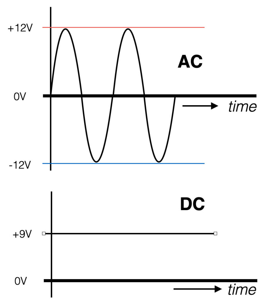
A power-supply takes its energy from the wall-socket (in Europe 230V AC/50Hz / USA and Japan 110VAC/60Hz) and converts this into low voltage DC.  So before we have a power-supply that provides us with (let’s say) +9VDC, there are some important steps to take.

Transformer

The first thing is to transform the 230V~ (Europe) down to (for example) 12V~. This is done by a transformer. A transformer is in its fundamental a piece of metal with two coils wound around it. See the picture (thanks Wiki).  The red wire is the primary winding and the blue wire is the secondary winding.

The red wire is connected to the mains (230V~) and is inducing a magnetic Flux within the metal core (green dotted line). In the blue wire, wound around the same metal core, an electric current will flow (induced) because of this magnetic flux. If the amount of windings on the primary side (N1) is equal to the amount of windings of the secondary side (N2), the voltage on the input and output are equal. But let’s say the primary coil has 1000 windings and the secondary coil has 100 windings, the output voltage (the secondary voltage) will be 23V~ (230 * 1/10). So the proportion of the primary and secondary windings ( N1/N2) determine to which value the voltage is transformed. In practise there are values that vary from 6V~, 9V~, 12V~, 15V~, 18V~, 24V~, … Note that the output (~) is still an AC signal. It has a smaller amplitude but it still has the same frequency (50Hz).

Important notice is that a transformer only works for AC! 
Since the coil is just a long wire, it’s (dc) resistance is low and when a DC-voltage is applied, the current will be too high (the coil can burn). For AC-signals a coil acts as a resistor, so for AC the current will be low(er).
The other reason why only alternating signals works for a transformer, is that we need alternating current to create a constant changing magnetic field (flux). Due to this changing magnetic filed, a current will be induced in the secondary coil.

Recitification

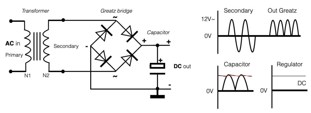
The next step in the design of a dc-power-supply is to ‘rectify’ this low secondary AC-output of the transformer and change it into a DC-signal. This is achieved with the use of 4 diodes actually placed into a bridge-circuit, also called Greatz circuit. These 4 diodes connected to an AC-signal will double rectify the AC-signal. If a big capacitor is placed parallel to the output of the diode-bridge, the rectified output will be smoothed and the ‘gaps’ between will be filled. See the figure below.

Voltage regulation

The setup above shows the very standard and simple power-supply setup. The DC output of this setup still has some ‘ripple’ (= dsiturbance) on top of the DC signal (see the ‘capacitor’ part of the graph). To make a ‘perfect’ straight DC output, we make use of so called regulators.

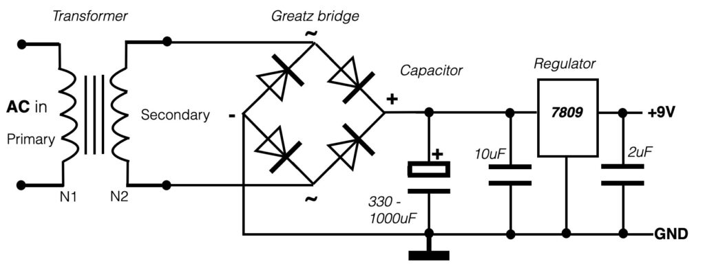
Regulators, like the ‘7809’ in the example above,  do come in all kind of forms or shapes. The 78XX series are positive regulators and the number (XX) determines the value of the voltage they will regulate. Of course this is only possible if the voltage in the input is higher than the regulated output. In general the difference between the in- and the output should be at least 2,5V. The capacitors used on the in- and output of the regulator are here to avoid oscillation and they are placed as near the regulator as possible. The power supply with only +9V output is also called a ‘unbalanced’ power supply. It is only one value.

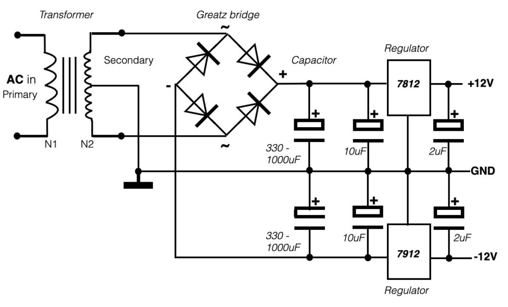
If you want to work with audio circuits you most likely need a balanced power supply. This is a supply that provides you with both plus and minus values. An example below:


Single sided power

Unbalanced power supply

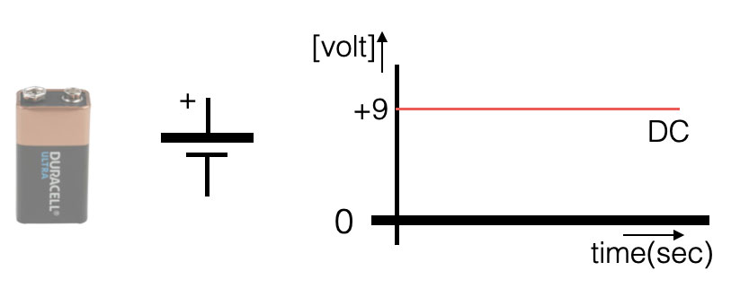
When you are in need to power your circuit, most of the time you will use a battery (or a powersupply as decribed above). A single battery provides you with only (for example) +9V DC in relation to the 0V – hence the plus and the minus connection. Take a look at the picture below.

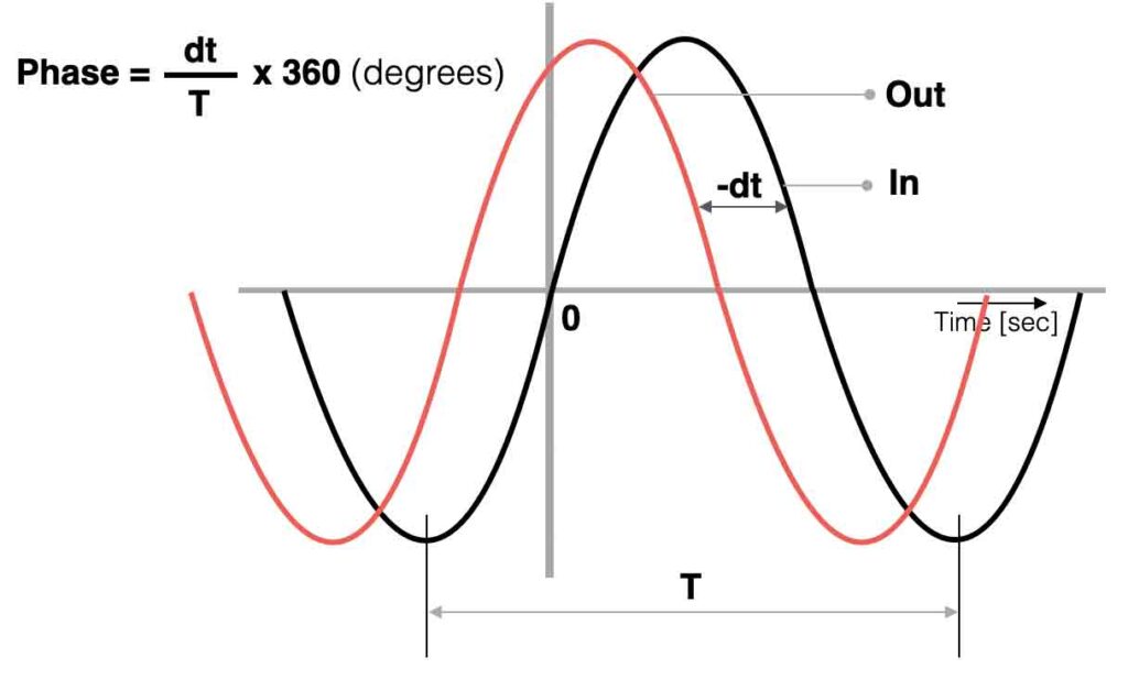
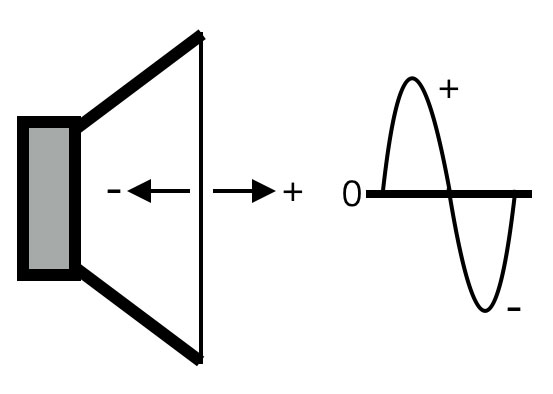
For a lot of circuits this single battery will be fine. It can provide the circuit with 9V and a small current of (more or less) 100mA. If you want to power an audio circuit (opamps for example) with only one battery, then you will encounter a challenge. An audio signal (AC) is positive AND negative! If you think about a speaker that generates sound, the membrane of the speaker will move forwards but also backward – through the zero (rest) point. See the picture below with a speaker moving forward (+) and backward (-).

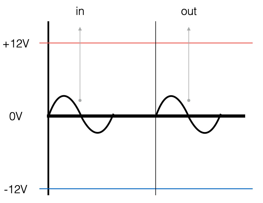
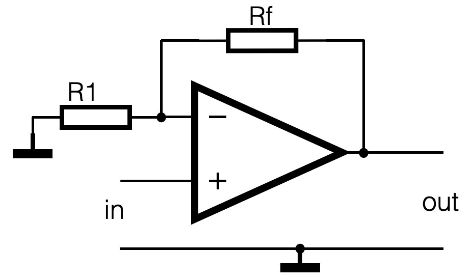
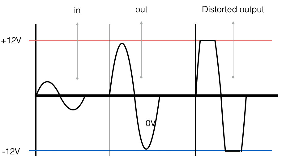
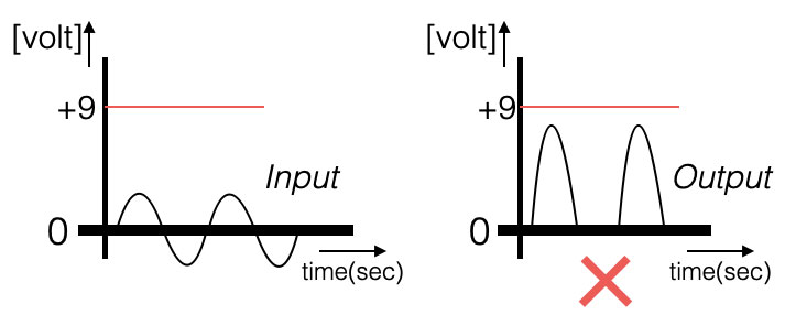
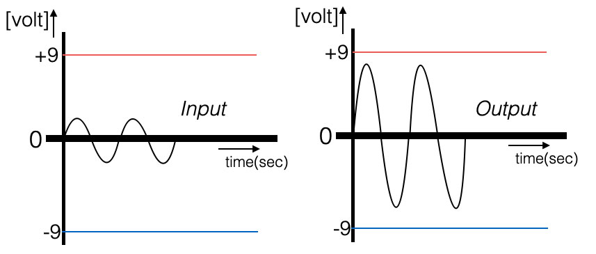
A circuit that amplifies an audio signal needs to have ‘balanced power’. A single-sideded powersupply (like a battery) can not provide this- it is only positive. If you would connect an audio amplifier to a single sided powersupply, the picture below shows what will happen:

The negative part of the sinewave cannot be amplified, because there is no negative power! So how can we make sure that the negative part of the sinewave will be amplified as well? The answer: use a balanced power supply. This is a power supply with two sources, placed in series.

Double sided power supply

Balanced power supply

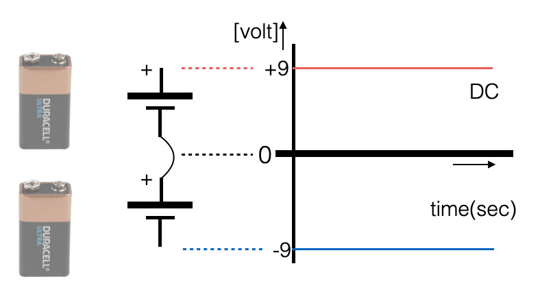
If we take two batteries (or voltage sources) and place them ‘in series’, we actually create 3 points. We have the plus, the zero and the minus. In general plus (+) is indicated with red, ground or zero with black and negative (minus) with blue.

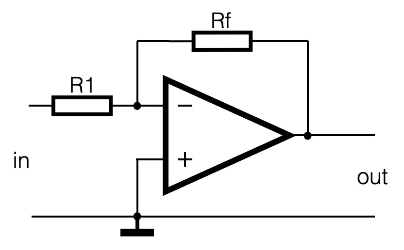
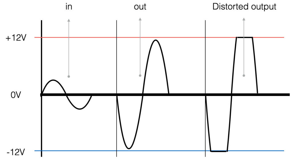
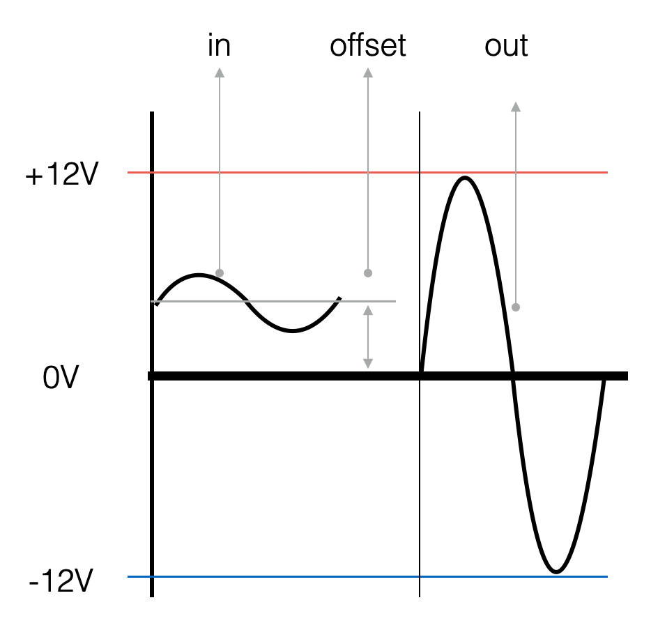
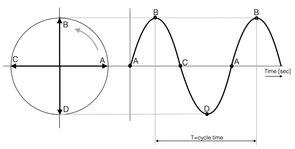
IF we now want to amplify a sinewave, we have positive AND negative power available and the audio signal can be streched up and down. See the graph below.

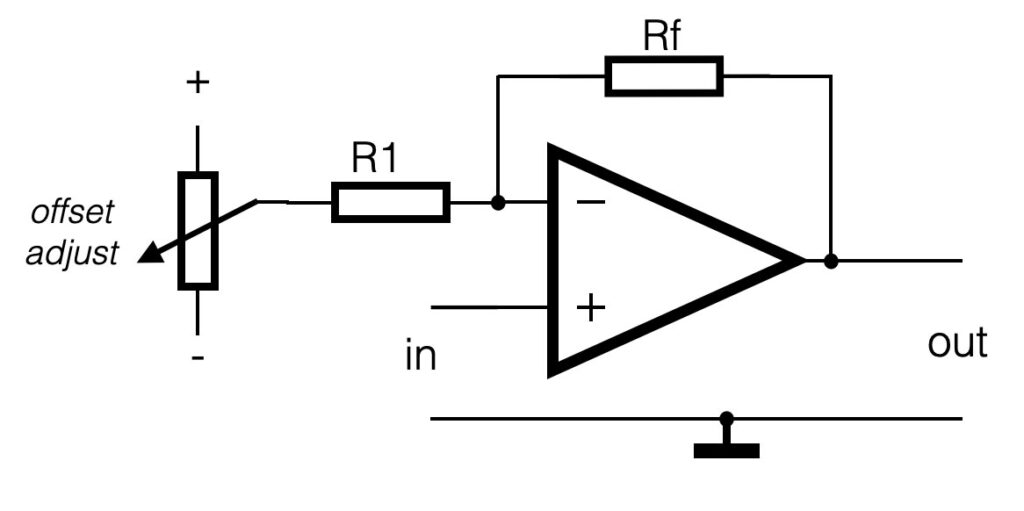
Create simple balanced power

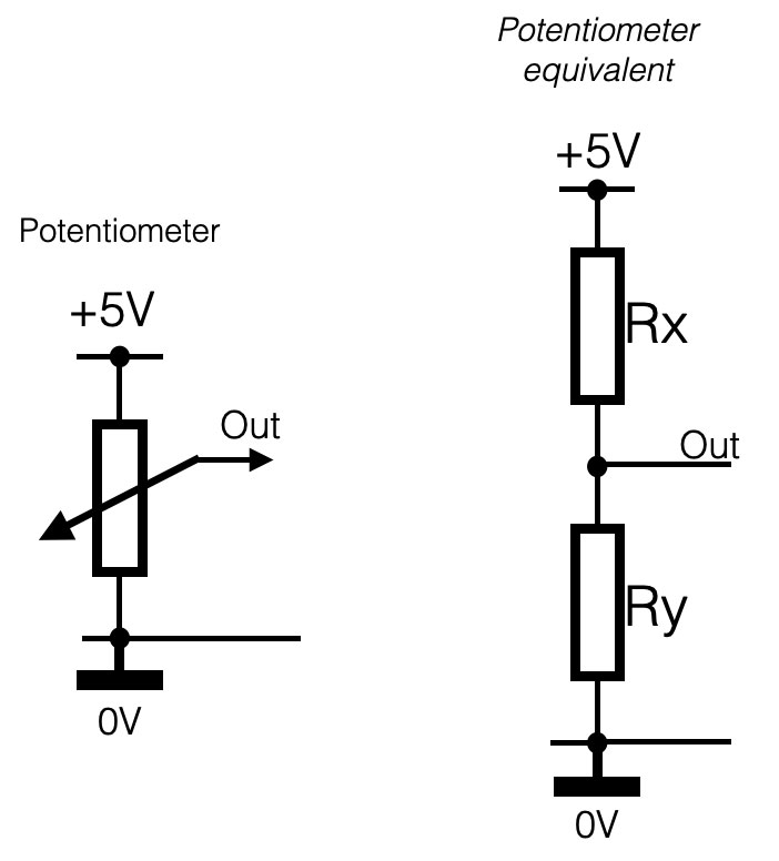
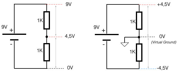
There is also a possibility or ‘trick’ to avoid the use of two power sources or batteries. Like explained in the fundamentals and ‘Ohms law’, you can also create a voltage divider with two resistors. The two resistors divide the voltage in two equal parts, e.a. 9V divided by two creates two times 4,5V. See the image below:

The middle point (0V) can now be used as ‘ vritual ground or ‘signal ground. In reference to that point you have +4,5V and -4,5V. We have balanced power. The signal-ground (virtual ground) should not be mistaken for the real ground. It still has a potential voltage of 4,5V. Circuits tat make use of this setup always have to apply a capacitor to get rid of the DC component.

eVideos

Some useful video tutorials

Diodes explained
Transformers explained
Transistors explained
How do MosFets work?
How does a Potentiometer work?
DC-motor, how do they work?
Ohm’s law explained
Binary counting and computing

How do conductors (coils) work?
How does electricity work?
How logic gates work
How does an Antenna work?