In the digital-electronics world it all is about ‘ones’ and ‘zeroes’. It’s about ‘Yes’ or ‘No’. There is no ‘Maybe’! Computers work with digital data that only consists of bits and combination of bits, called bytes. A bit can only have two values: ‘0’ or ‘1’. In electronics this means 0V or 5V (TTL). Since the development of mobile technology, nowadays lots of computers (e.a. phones) work with 3.3V logic.
The fundamentals of digital electronics starts with the different logic ports called NOT, AND, NAND, OR, NOR , XOR and XNOR. With combinations of logic ports, complex logic function’s can be created. If a lot of these ports are combined (millions…) in one chip, microprocessors and computers are created.
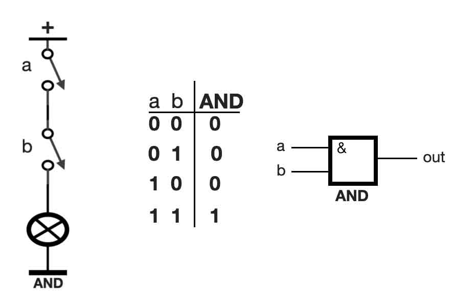
AND port
Let’s start with the basic port called AND. An AND port can be seen as two switches that are connected in series. See the figure below, the left side. If both switches ‘a’ and ‘b’ are OFF (also referred to as 0), the lamp (the circle with the cross) will not light up – it’s also OFF (= 0). If switch ‘a’ is ON (= 1), and switch ‘b’ is OFF (= 0), the lamp is still OFF. We can put these different values in a so called truth table, see the tabel in the middle. On the right side the European symbol of an AND port is shown.
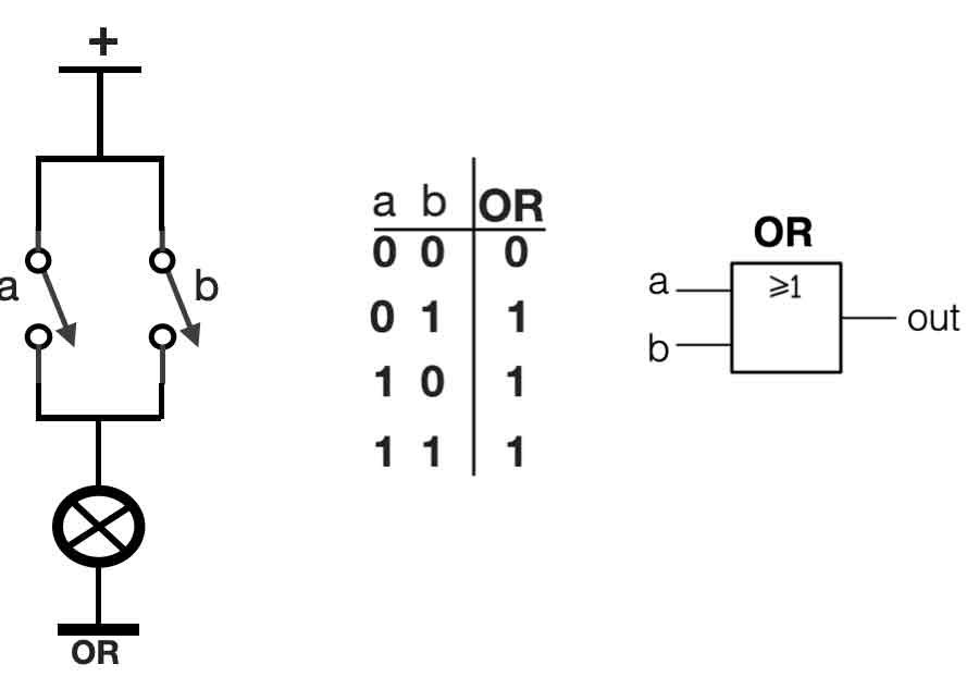
OR port
An OR-port is a combination of two switches connected parallel. See the left side of the figure. This gives another truth-table. If only one switch ‘a’ or ‘b’ is in the ON position ( = 1), the outcome will be 1. See the figure below:
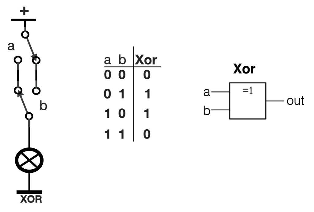
XOR-port
The XOR-port is also called an ‘Exclusive OR’ port. This port consists of two switches both with two poles. The setup of this two switches is that with both of you can switch the light ON or OFF. This circuit is often applied in rooms where you can switch the light ON at the door and switch the same light OFF on the other side of the room – it’s practical. Take a look at the figure below. In the XOR-port the light is only ON when both switches ‘a’ and ‘b’ are in the oposite position. In case of the picture below the switches are in the same position (upside down) – thus the result is “0”.
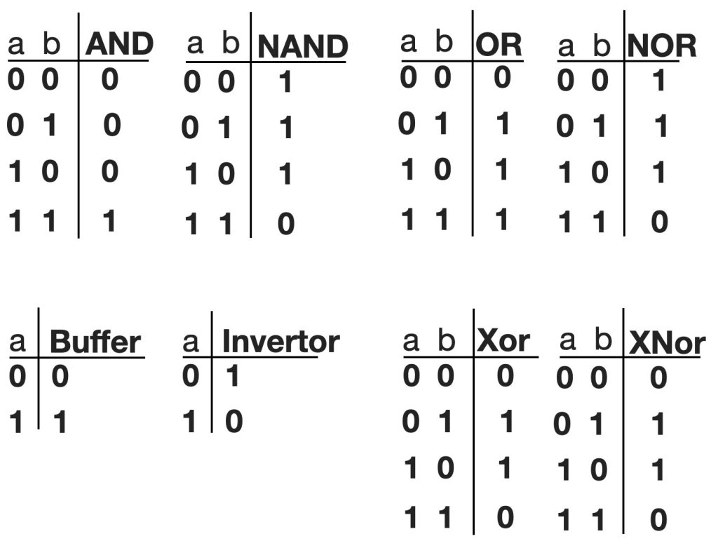
A port overview
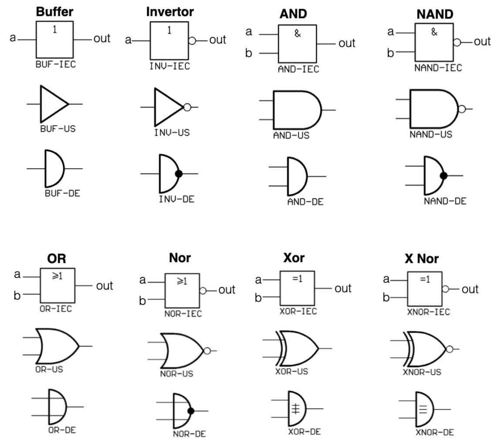
All the ports mentioned above also have their ‘INVERSE’. This means the opposite of the values in the normal state. For an AND the inverse is called a NAND. An OR port inverted version is called a NOR and a XOR inverted is a XNOR.
There are also ports that only invert – so called inverters. A logic ‘one’ on the input creates a logic ‘0’ on the output and vice versa – always the inverse. There are even ports that do not change the state of a signal. In other words, a logic ‘0’ on the input creates also a logic ‘0’ on the output. These ports are called buffers.
And below an overview of all the symbols of the logic ports. In Europe and the USA they use different kind of symbols – for the same logic ports. This can be confusing.
Binairy counting and resolution
With the logic ports mentioned above a lot of great functions can realized. Like decimal counters, dividers, binary counters, shift registers and much more.
So what is counting in the digital world? How can we count and make big numbers with with only 2 bits? First of all we need to use the binary counting system. This system only has two symbols (binary) a ‘0’ and a ‘1’. Our decimal system has 10 symbols (dec). We start with 0 and count till 9. After 9 we combine the first two symbols 1 and 0 , making 10. The same mechanism we apply to binary counting. Starting with 0, 1 and the combine the first two: 10. After that we get 11 and then we combine again: 100.
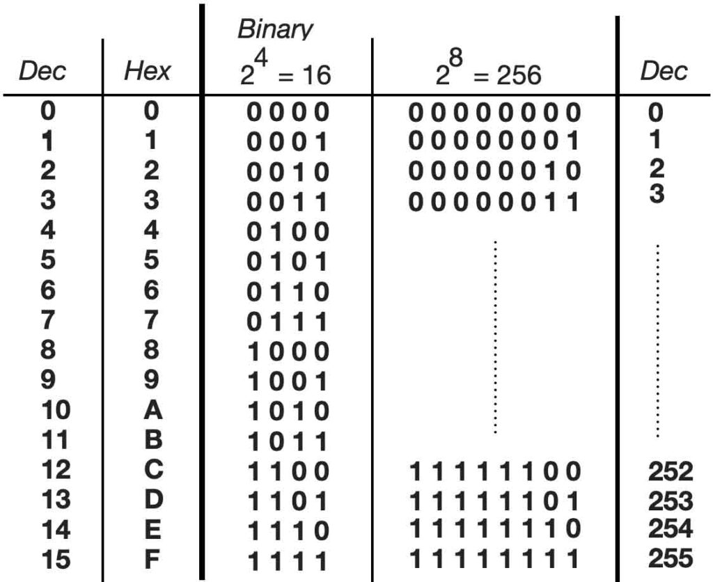
Take a look at the table below. On the left side the decimal numbers 0 – 15. In the middle the equivalent binary numbers starting with 0000 (=0 decimal) and ending with 1111 (= 15 decimal). So with a 4 bit ‘resolution’ (= 4 bits = 24) we can make numbers from 0 to 15 (equal to 16 numbers, zero included). If we double the amount of bits (=8 bits = 28) we can make numbers between 0 and 255. The higher the resolution, the higher number-range can be made. If we talk about 8 bits, we could also call this one byte.
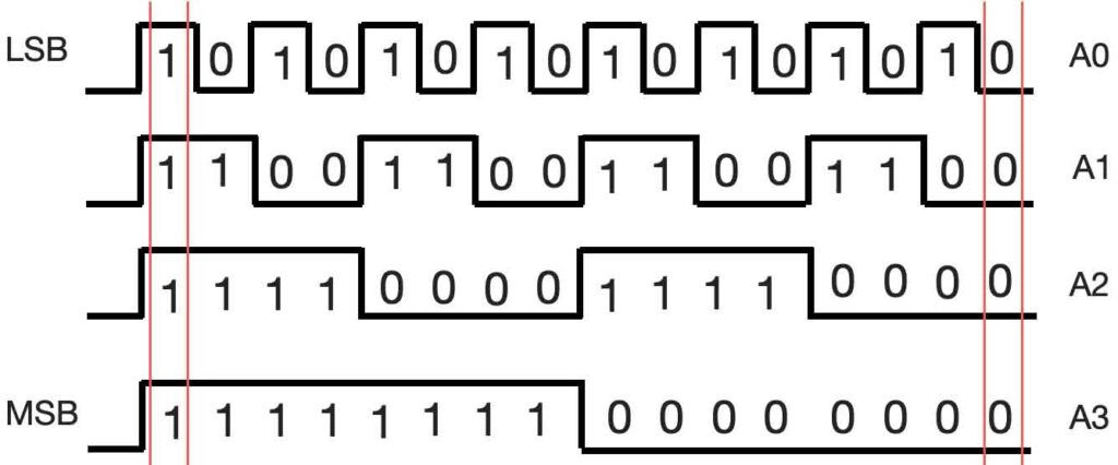
When we take a closer look at the binary series in the table above, you can see that the most right ‘bit’ constantly changes between 0 and 1. We also call this bit the LSB (= Least Significant Bit). The next row is changing every two numbers: 00 11 00 11 … (division by two). The third row is again divided by two: 0000 1111 0000 1111. The fourth again, etc etc. The row on the most left side we call the MSB (most significant Bit). When we create ‘dividers’ with the logic ports, we can create binary counting. Take a look at the figure below.
The upper row is the LSB, changing constantly between 0 and 1. The row below (A1) is divided by two resulting in 00 11 00 11… If we look at the numbers on the right side, from top to bottom, we see 0000 (=dec 0). One pulse to the left we see 0001 (=dec 1). Completely on the left side we see 1111 (=dec 15).
There are a lot of different digital ‘chips’ available with already pre-made logic functions. The most common range is the 7400 range and the 4000 range. The 7400-series is so called Transistor Transistor Logic (TTL) and can only with +5V (=1) and 0V (=0). The HEF4000 series is based on MOS (Metal Oxide Semiconductor) and can handle a voltage range between 3 and 18V (depending in the specifications).
More information about digital electronics, check this.
If you want to check your circuit you need to tools to ‘look’ at your circuit and check whether the values are correct. Is it the right voltage? How big is the current and what is the exact shape of the AC signal? For these measurements you need tools.
Multimeter
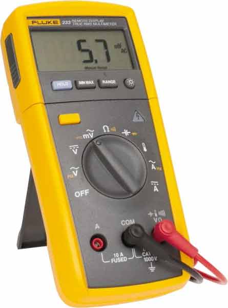
The most common tool to measure values in a circuit is the multimeter. With a multimeter you can measure the voltage (AC or DC), the current (AC or DC), the resistance and depending on the model also the capacity or some semi-conductor values.
Another important feature is the ‘beep’ function. With this function you can check the connection between two points. It has the symbol of a diode – it is a diode check function at the same time.
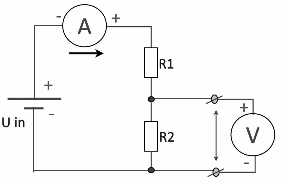
Important to know is the following: when you measure the voltage (V) in a circuit you always do this parallel (see the picture below). This means the resistance between the two measuring clips is ‘infinitely’ high – otherwise the multimeter would influence the behavior of the circuit and that is not acceptable.
As shown in the ‘voltage divider’ circuit above, the current (A) is measured in series. The current flows through the multimeter and therefor the resistance of the multimeter in current-mode is 0 Ohms.
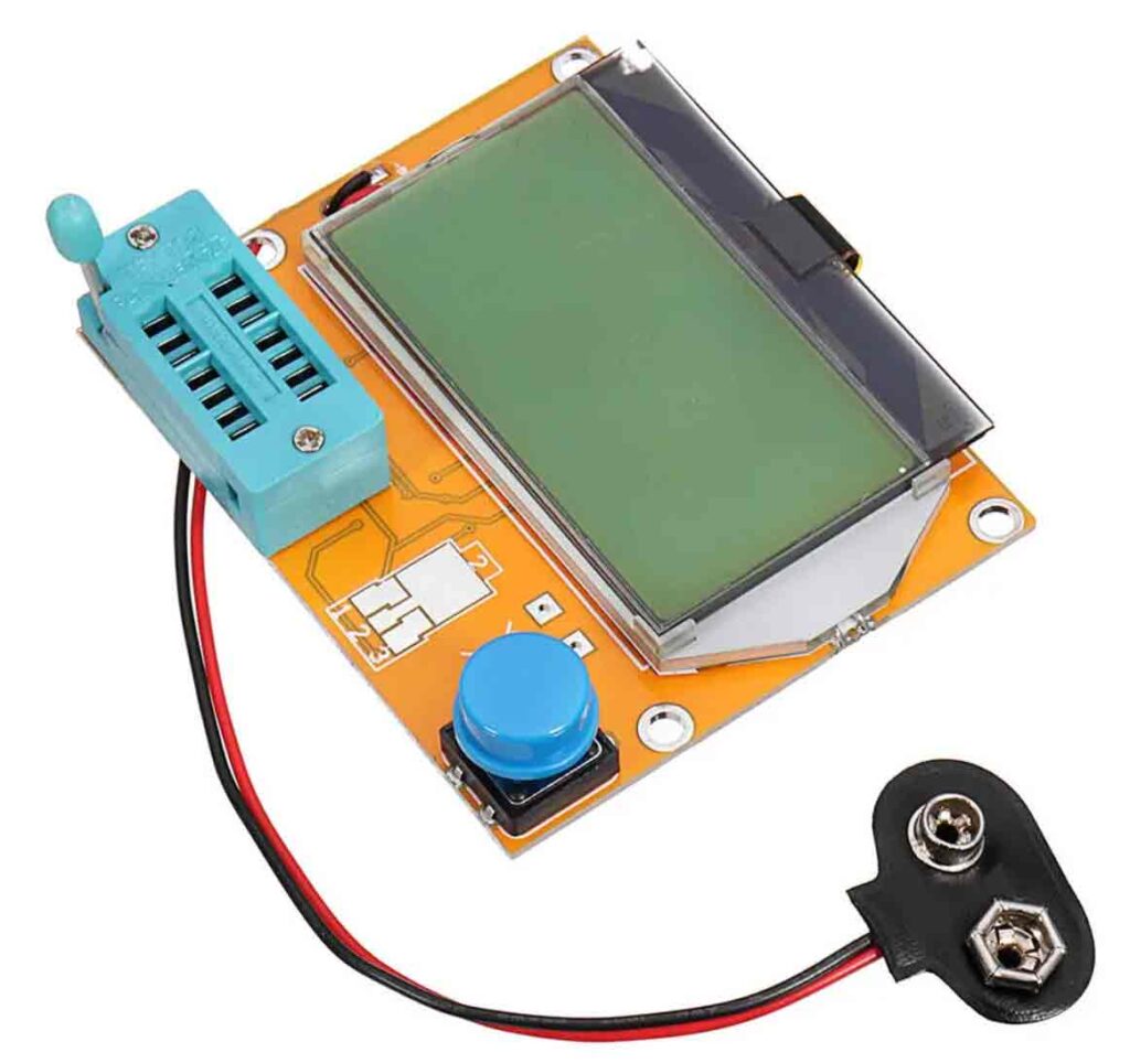
Component tester
One of the tools that really is practical and cheap, is the component tester shown below.. With this tester you can determine the value of a resistor (ignoring the colour codes:), test the values of capacitors. coils, transistors and fet’s. Very practical.
The oscilloscope
The oscilloscope is the main measuring tool to help you ‘look’ at the signals within the circuit. The screen is divided into small block called Divisions. Most of the oscilloscopes have two inputs. This way it’s easier to compare signals with each other.
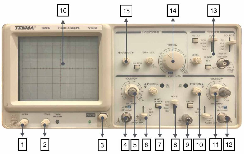
The most important keys on a scope are the “Volt/Division” setting the vertical value of the signal and the Time/Div knob setting the horizontal value. Depending on the value the knobs are indicating, the value of the signals can be read. Below a picture of the oscilloscope we will use during the lessons.
1. Changes the light-intensity of the screen 2. Focus the screen 3. Power On/Off 4. Input channel 1 5. Volts/Div channel 1 6. AC/GND/DC selection 7. Chop/Alternate 8. Input selection Ch1,Ch2, Dual, Add
9. Ground connection 10. Position beam channel 2 11. Volts/Div channel 2 12. Input Channel 2 13. Trigger section 14.Time/Div setting 15. Horizontal position screen 16. Screen with 10 x 8 divisions
Quiz question 🙂
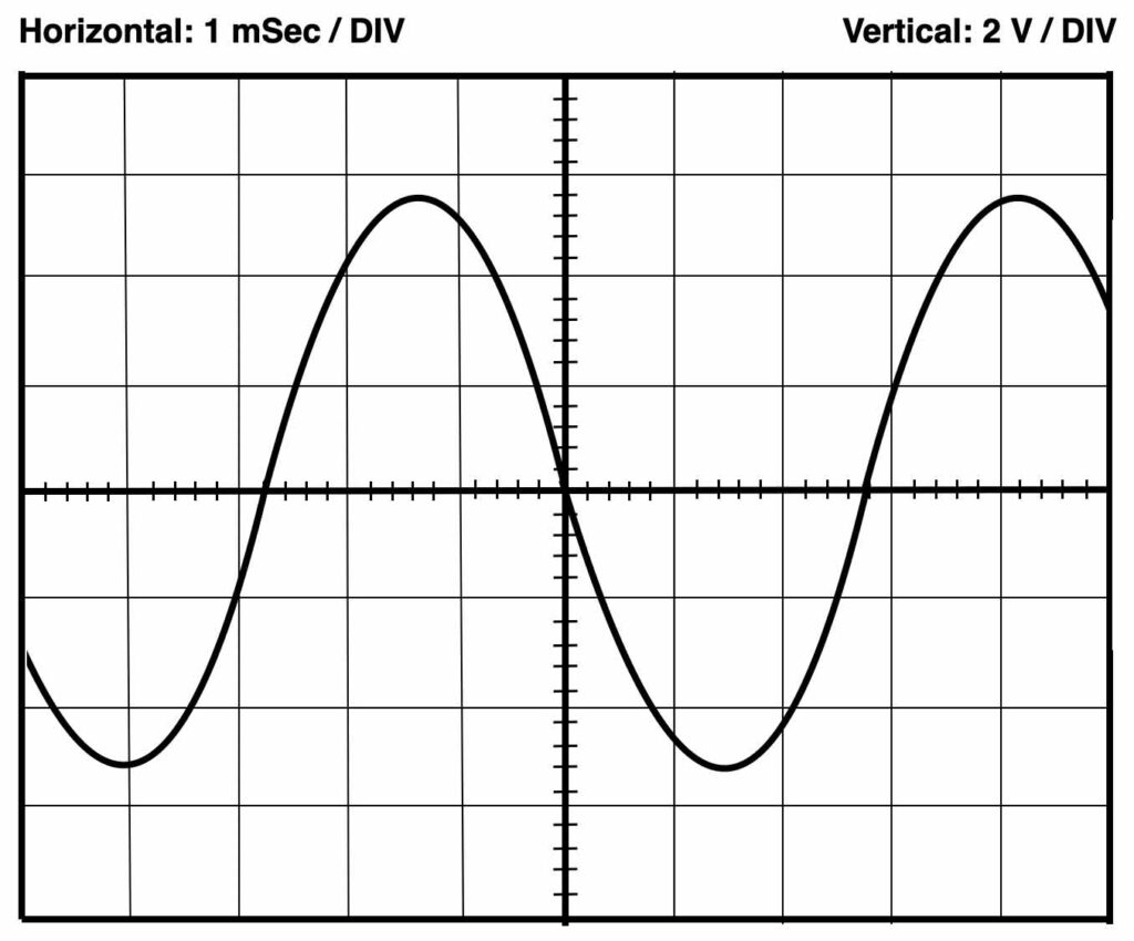
Below a sample screen of the oscilloscope. Can you determine the right frequency? The Volts/Div and Time/Div settings are indicated on top.
This section introduces the serial protocol as a means to communicate with the Arduino by receiving messages from it, or by sending instructions to it. Its use here is explained from the perspective of using Max or Pd as interfaces. An examples of how to connect to Supercollider can be found here.
In order to establish communication with the Arduino, a serial protocol is used. This protocol is used for uploading instructions to the Arduino, but can also be part of an interaction scheme, for instance when sensor values need to be visualized in a user interface. The serial communication can be explained in its most basic form as a transport line of individual characters between the Arduino and a computer. It is possible to deviate from this basic form; that will be explained in another section in the future.
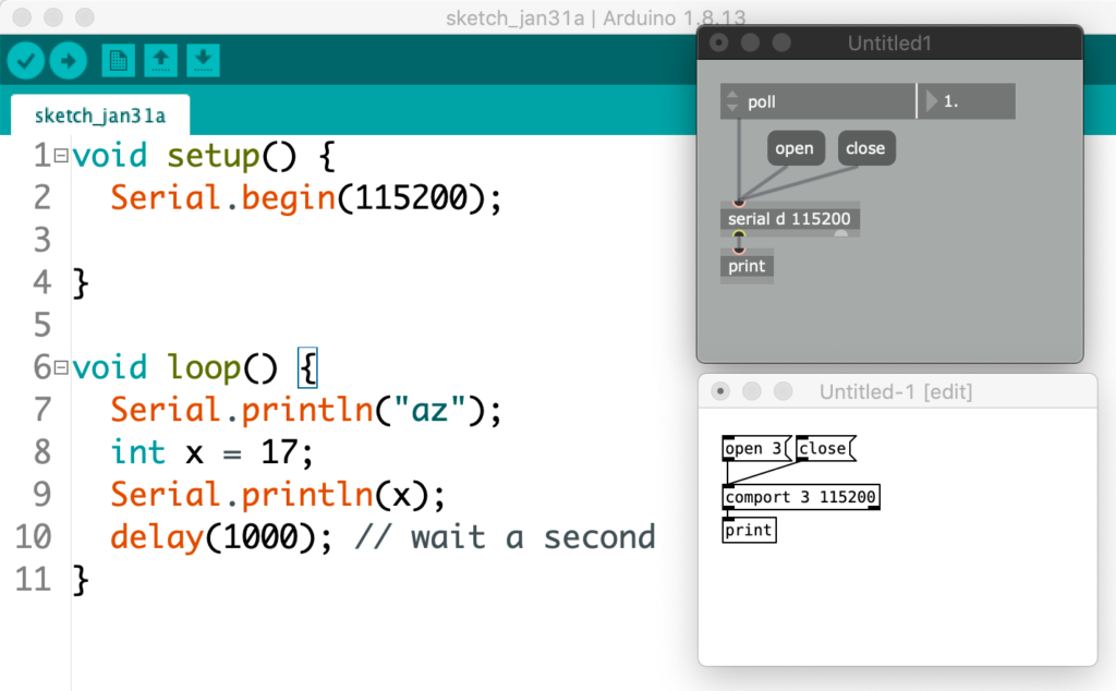
This section explains how to set up such basic communication between the Arduino board and the applications Max and Pd. Since these platforms are rather similar, patches for Max and Pd look somewhat identical. The Arduino can send data to Max or Pd, or it can receive data from it. In either case, data is represented by individual characters that are sent one at a time. Rather than the actual character, the transport line expects a numerical representation of that character. These representations are stored in a so called ASCII (pronounce: askey) table, which binds e.g. the letter ‘A’ to the value 65, or the character ‘7’ to the value 55. When sending data from Arduino, those ASCII representations remain obscure. All that is required is using the Serial.println command.
Serial.println("az");
int x = 17;
Serial.println(x);
The three lines above represents Arduino code that first sends the letters ‘a’ and ‘z’ over the serial port, and after that the value for x, which is 17, is sent. As said before, when sending, nothing shows that println uses ASCII representations. But at the receiving end, is will be ASCII that is received. The objects used are serial in Max and comport in Pd. The comport object is not vanilla and needs to be installed. Here is a how-to.
Max (left) and Pd (right) — connecting to a serial port
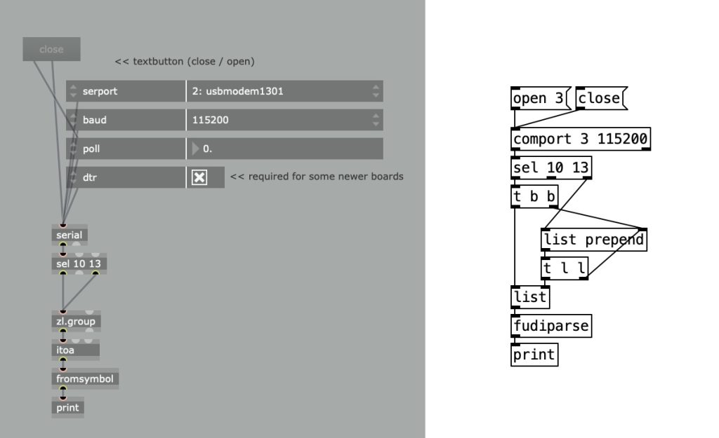
The connection to the serial port is created by providing a port reference. In Max this is a letter, and in Pd a number. With a specific message the information on available ports and their references can be printed. Arduino’s serial port is typically listed as ‘usbmodem’. The next step is to provide this identifier as argument, as well as the speed at which the communication is set up. The patches below show just this. The Max object that reads ‘poll’ is an attrui and is the easiest way to get data from serial.
Serial data sent to Max or Pd
The numbers that are printed out are in order: 97, 122, 13, 10, 49, 55, 13 and 10. After one second the exact same sequence appears. These values represent characters according to the before mentioned ASCII table. According to this table, the values 97 and 122 represent the characters ‘a’ and ‘z’, the values 49 and 55 the characters ‘1’ and ‘7’—indeed, numerical values are sent as individual characters. It is easy to see how this accords with the messages sent from the Arduino code. Twice, a combination of 13 and 10 appears. The ASCI table names these values ‘line feed’ (LF) and ‘carriage return’ (CR) respectively—terminology that suggests printer activity. These two values are inherent to the Arduino ‘println’ command and can be used in our patches as indicators that a complete message has been received.
Printing interpreted data from the serial connection
Max and Pd can transform the ascii values to the characters they represent using respectively the atoi and fudiparse object. Copy the code below into a Max patcher window to create the patch above.
Important to take into account is that only a single application at a time can connect with the Arduino board over the serial connection. In order to allow one application to open the connection, another must close it.
Telling apart multiple sensor values
When reading out multiple sensor values in Max or Pd, another approach than simply using println() must be adopted. In order to know which value represents the first sensor and which the second, the values are better send in such a way that they create a list. In Max/Pd a list can be specified as values separated by a space. The Arduino code shows how to create the spacing. Only after the last value has been sent, a println() is used to create a flag for the receiving end.
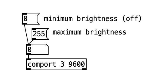
The section above explains how Max or Pd receive values from the Arduino. Communication in the other directions is possible too; from Max/Pd to Arduino. The dimmer example shows how this communication can be used to adjust the brightness of an LED by sending a changing value in the range from 0 to 255. This value is used to change the setting of a PWM value. Not much coding is Max/Pd is required to achieve this, simply connect a number box to the serial/comport object. The Arduino example even includes Max code that can directly be pasted into an empty patcher window.
Sending values over serial
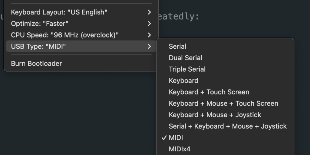
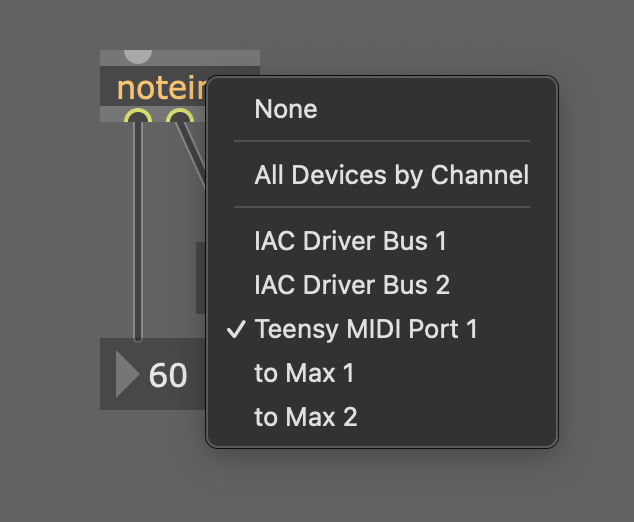
Example: using a Teensy as a MIDI controller
The MIDI data that can be transmitted between musical controllers and computers, is essentially a variation on the serial protocol. The Teensy development board—which is like an Arduino–can easily be turned into a class compliant MIDI device, which means that it can function as a MIDI interface without having to install drivers.
From the Arduino IDE, through the ‘Tools’ menu, the ‘USB Type’ can be set to MIDI. With the next upload, the Teensy will turn into a MIDI device and will be recognized as such by applications like Max, PureData or SuperCollider.
The code below extends the blink example so that it sends a MIDI note.
After uploading this code, Max will see the Teensy as a MIDI input, and pass the values as expected.
Example: fading an LED with potmeter
The fade example automatically fades the brightness of an LED between minimum and maximum. Closer examination reveals that although the pwm values used to fade are linearly increasing and decreasing, the change of light intensity appears not to be linear at all. If the left image below shows the linear change of pwm, the right image represents what the light intensity actually looks like; jumping rather quickly to high intensity and then slowing down while it reaches maximum value.
If linear intensity change is desired, it would be better to adjust the pwm values. Max provides a fine environment to prototype this. An audio rate oscillator provides the source of values. A potentiometer connected to A0, can provide a value for the speed of this oscillator. The patch below is an example of how to connect everything together. By raising the oscillator value to the power of three, we achieve a change of brightness that appears to linear.
A Max patch for adjusting speed of brightness change
Adjusting the brightness of an LED, as explained above, can be turned into adjusting the speed of a motor. But in order to extend this model to multiple motors, another approach needs to be taken. What we need to solve is how to connect multiple number boxes to equally as many PWM driven outputs.
The solution lies in creating a separate function for dealing with incoming serial data with serialEvent(). The Serial Event example demonstrates the use of this function. A Max or Pd patch now sends various values separated by spaces, using an ascii representation. In this representation the space and return values function as flags that trigger the pushing of values into an array and updating the values to be written to the outputs.
int motorPins[] = {9, 10, 11}; // pwm pins
int motorCount = 3;
byte motorSpeeds[3]; // reserve space for three bytes
int motorIndex = 0;
String inputString = "";
bool dataComplete = false;

void setup() {
  Serial.begin(115200);
  // declare all pins as outputs:
  for (int i=0; i<motorCount; i+=1) {
    pinMode(motorPins[i], OUTPUT);
  }
  inputString.reserve(3);
}

void loop() {
  if (dataComplete) {
    for (int i=0; i<motorCount; i+=1) {
      analogWrite(motorPins[i], motorSpeeds[i]);
    }
    dataComplete = false;
  }
}

void serialEvent() {
  while (Serial.available()) {
    char inChar = Serial.read();
    switch (inChar) {
      case 32: // space
        motorSpeeds[motorIndex] = inputString.toInt();
        motorIndex += 1; // increase index
        inputString = ""; // reset string
        break;
      case 13: // new line
        motorSpeeds[motorIndex] = inputString.toInt();
        dataComplete = true;
        motorIndex = 0; // reset index
        inputString = ""; // reset string
        break;
      default:
        inputString += inChar; // add character to string
    }
  }
}
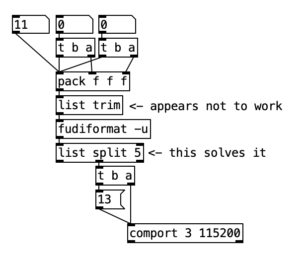
The Pd patch below works with the above code. However, the fudiformat object generates additional data to the extent that a list selector is included in the ascii values. Although the ‘list trim’ object promises to strip off this selector, that appears not to work. In order to solve this issue, an object ‘list split 5’ is added.
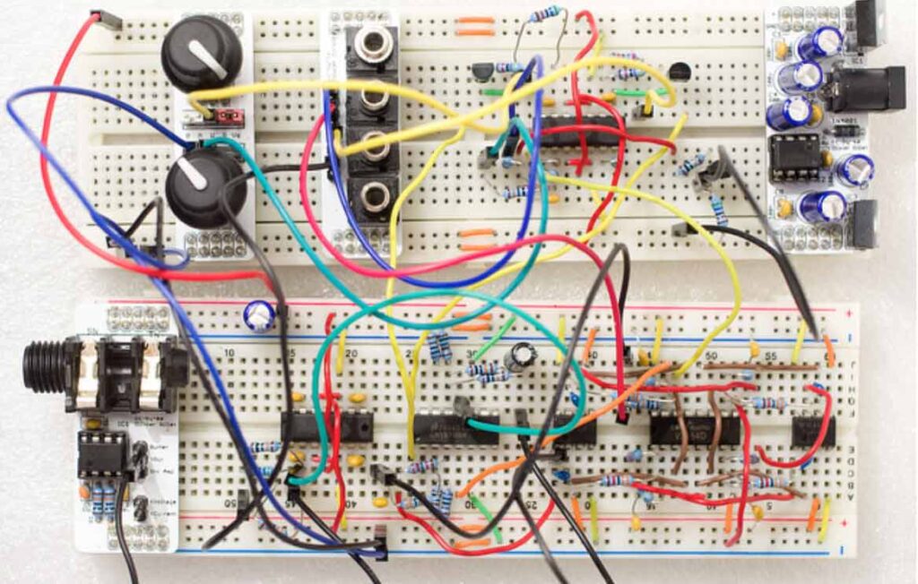
If you want to experiment with electronic circuits, a breadboard can really be of great help. Of course you can directly start with soldering components and wires togehther, but if you are not sure about the design, it’s very convenient to “connect and re-connect” without soldering hassle.
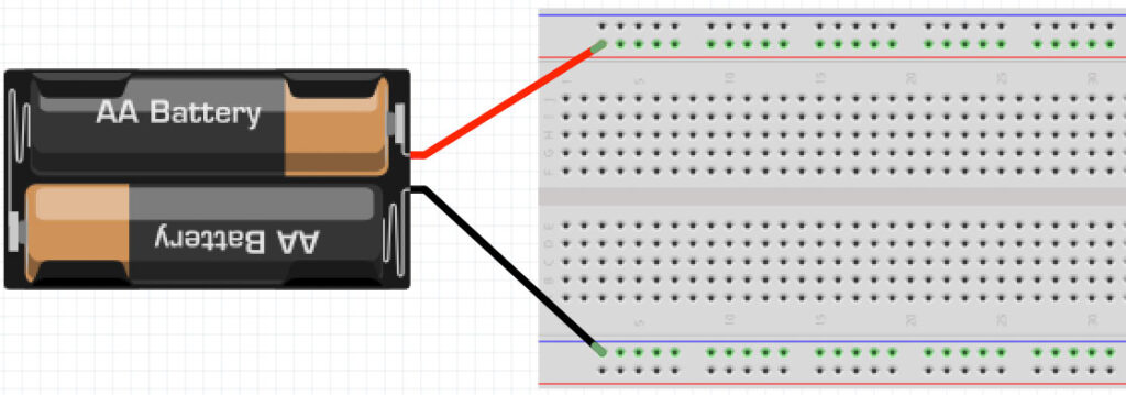
A breadboard is nothing more than a few metal strips with ‘clamps’ organized in a way that it is easy to make an electronic circuit. Take a look at the picture below. On the top and the bottom you see two horizontal lines. All four of these lines are separate electrical points (or nodes). These lines are mostly used to distribute the power of (for example) a battery. In case of the example below the plus line is connected to the upper hor. line and the minus to the lower hor. line. The vertical shorter lines in the middle also represent separate nodes.
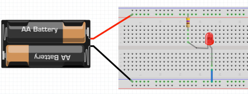
Below an example of the connection of a battery, a series-resistor and a LED.
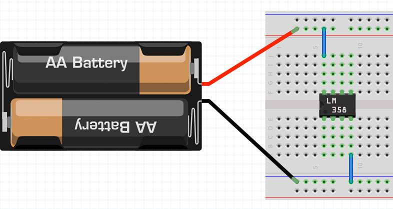
The breadboard is designed to also connect IC’s (Integrated Circuits). This is the reason why the upper vertical lines are not connected with the lower ones. Check this example:
The two pins of the chip (pin 4 and pin 8) are connected to the power lines. You can really create complex circuits on a breadboard.
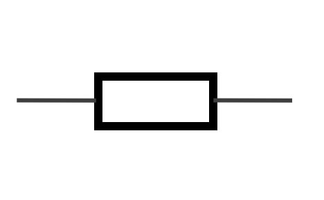
Wiki: “A resistor is a passive two-terminal electrical component that implements electrical resistance as a circuit element”. In other words, a resistor introduces resistance in a circuit. Resistors reduce the current in a circuit and introduce voltage division.
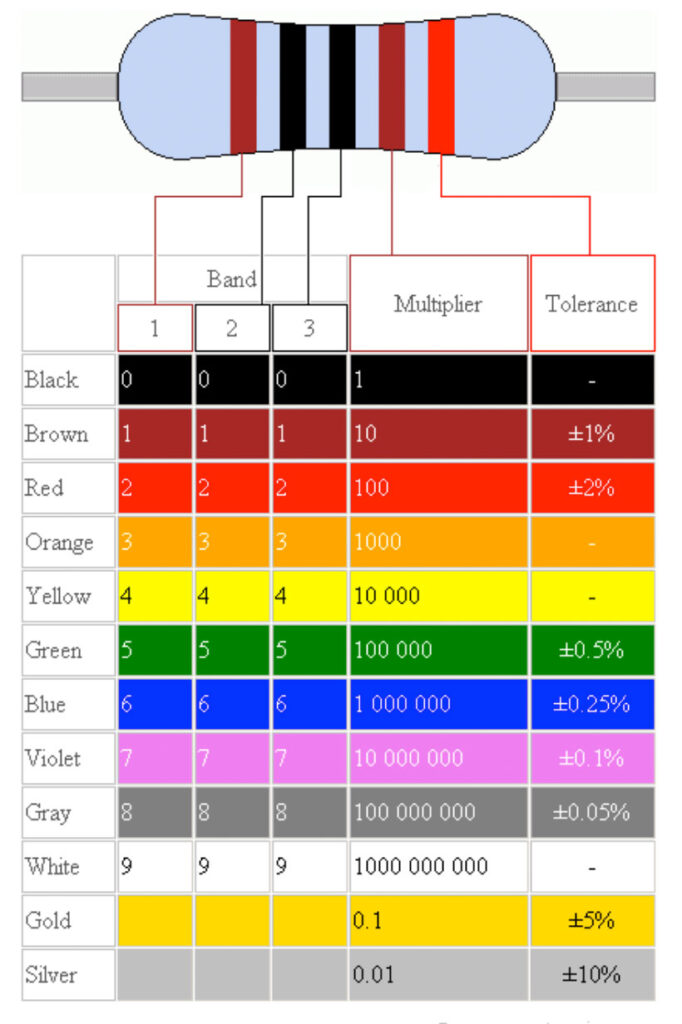
The value of resistors is determined by colored rings. In case of 1% resistors (the value can deviate 1% only) the value is given in 5 colors. Check the table below. The first 3 colors make the number. The 4th one is the multiplier. The 5th ring indicates the tolerance.
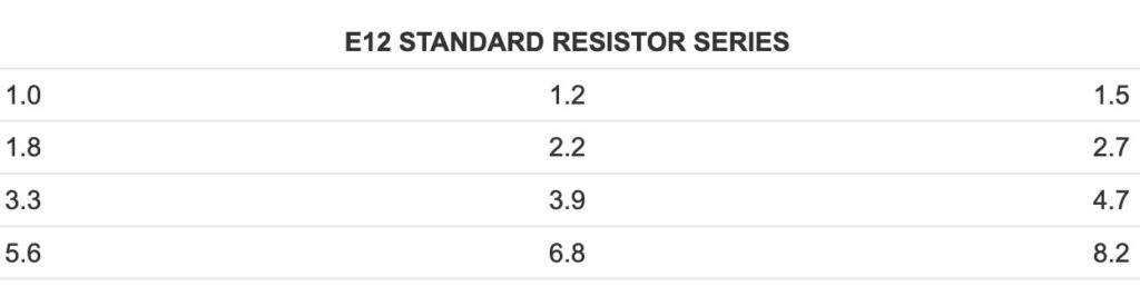
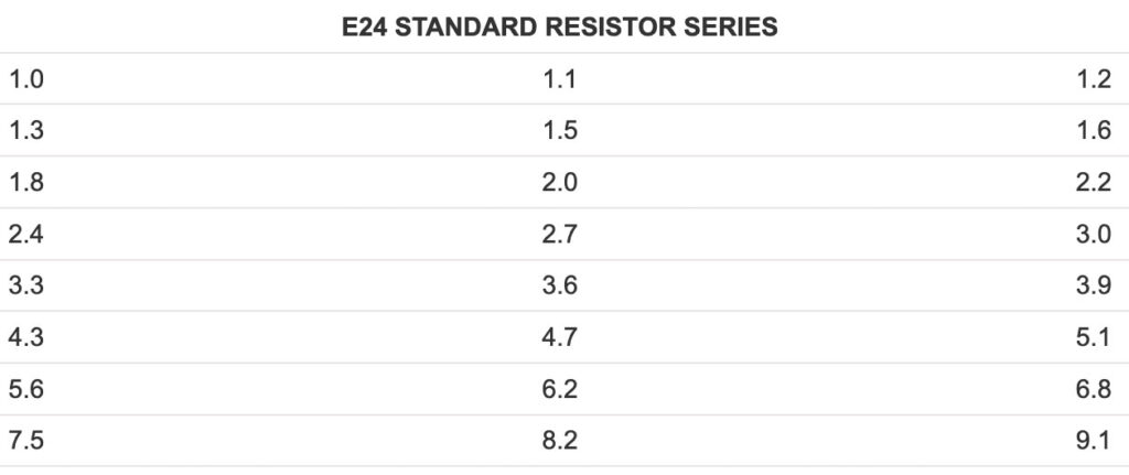
To simplify resistor manufacture, resistor values are arranged into standard resistor values conforming to the E series. This means you cannot go to the shop and buy any value you want – it is always part of a series. The most common series are E12, E24 or E96.
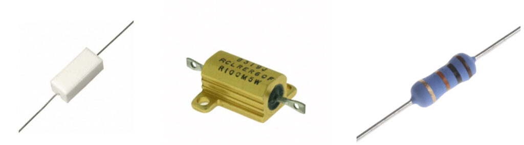
So for the E12 series you have 10k, 33k, 56M, … but NO 11k for example – because it is not part of the series. Resistors also have a maximum amount of energy they can dissipate. The normal small ones that you will find in audio-circuits are 0,125W (1/8W).
Sometimes you need resistors that can dissipate much more energy, so also the package will be different. See some examples below.
The invention of the transistor in the 1950’s changes the electronic world for ever. The transistor is a so called ‘semiconductor’ and is capable of amplifying signals. The transistor has a Collector (C), a base (B) and an emitter (E). It can be seen as a current controlled switch. A small current from the base to the emitter creates a bigger current (Ic) from the collector to the emitter. Take a look at this video-page, for a detailed explanation.
Imagine the transistoras the following setting: a large tube connected to a big pool of water. Halfway the tube there is a valve that can be changed position by a small tap on the side. Check figure 1.
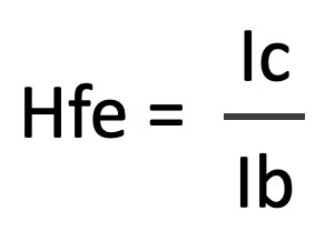
If there’s no base current (ib=0) the transistor is closed and there’s no collector-current. If the base current Ib is increasing (we turn the small tap on the side – Ib > 0), the water-flow (=current or Ic) will increase as well. Check figure 2. If the Ib is maximum, the collector current Ic is at its maximum as well. The proportion between Ib and Ic is called the Hfe. This number represents the amount of current amplification.
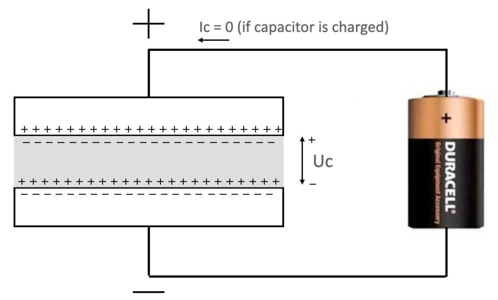
A capacitor is a passive component that consists of two metal (conducting) plates that are separated by a material called a dielectric. This dielectric is an electrical insulator that can be polarized by an applied electric field. The positive and negative particles inside the dielectric are not polarized if there’s no voltage applied.
The capacity of this component is measured in Fahrad. Common values in audio world are between 1pF – 10.000uF. When a DC voltage is applied to both sides of the capacitor, the capacitor will charge (look at the moved particles). For a very short time (time = 0) there will be a current flow that charges the capacitor. After the capacitor is charged, there will be no current anymore – until you change the polarity.
The capacitor is a super small chargeable battery.
Important to remember:
for DC voltages, the capacitor is a huge resistor or a blockade.
When an AC voltage is applied, the result will be different! Because of the changing direction of the current, the capacitor will be charged positive and charged negative and it will conduct the current in both ways. In other words: for ac-voltages (audio signals for example), the capacitor is a conductor. See the animation below.
Below an overview of the most common used cables within the audio world
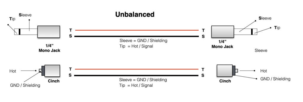
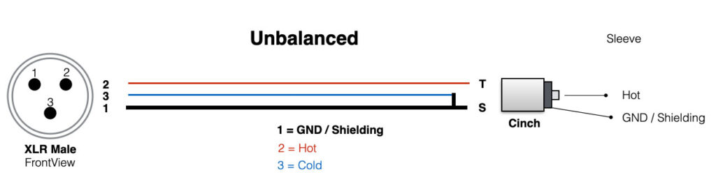
Unbalanced
The unbalanced cables are commonly used like the “jack-jack” (for synth or guitar/bass) or the cinch (RCA, tulip) cables. The small patch cables for a Doepfer system are unbalanced as well.
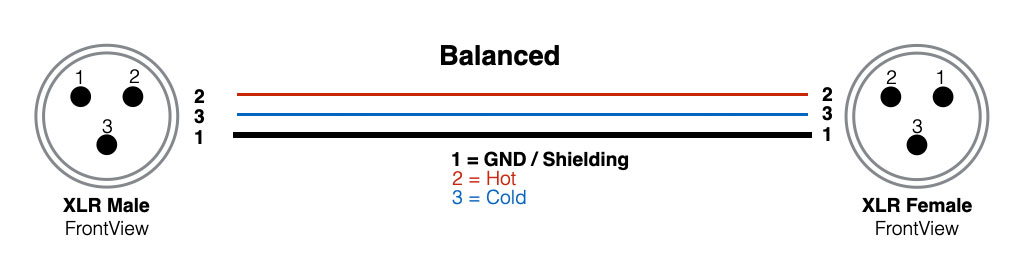
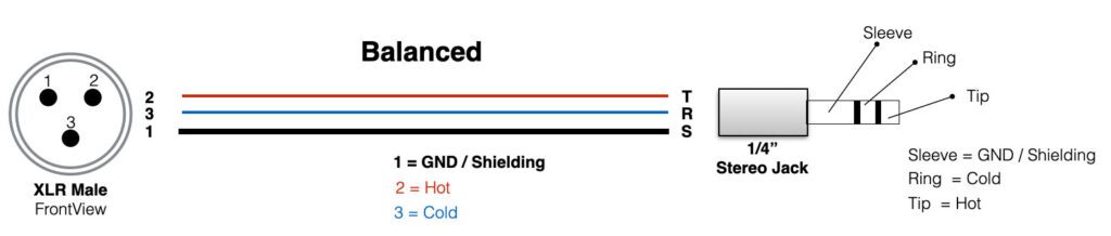
Balanced
Microphone cables, the XLR-cables, are balanced.
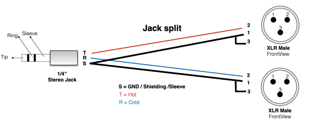
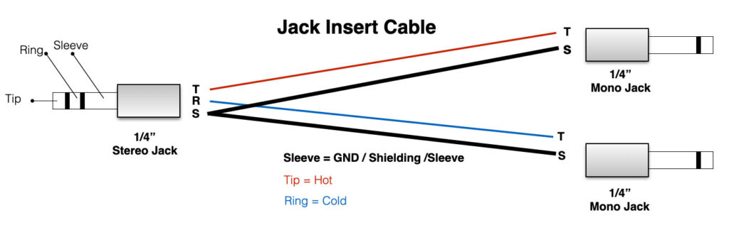
Split cables
If the output of a mixer or other device has to be split into two separate signals, we use split cables. An examples below.
In mixing-consoles it is possible to ‘insert’ effects. Belwo the example of an insert cable.
Electronics is an absolute fascinating world with the possibility to create any circuit and any functionality that you would like. But bear in mind: electronics can be very complex and frustrating as well. Circuits that do not work. Components that smell funny or circuits which are unstable. How do you cope with that? Let’s start with the fundamentals of electronics:
Wiki definition: Electronics deals with electrical circuits that involve active electrical components such as transistors, diodes and integrated circuits, and associated passive interconnection technologies. The nonlinear behavior of active components and their ability to control electron flows makes amplification of weak signals possible and electronics is widely used in information processing, telecommunications, and signal processing
Electronics is about the control of current in a circuit. If the current somewhere in the circuit is too small, it is not stable or not reliable. If the current too high, the temperature will be too high. It has to be somewhere in the middle. These lessons will give you a complete introduction to Electronics. We will focus on the basics and fundamental circuits that are applied in music and art. We will talk about the common applied components, passive and active and also the small programmable computers (Arduino, Teensy), or sensor interfaces will be part of the subjects.
Electrical current
All materials you can imagine are made out of atoms. The core of an atom is the nucleus which has protons and neutrons. In the outer shells there are electrons. Check the picture below.
Materials that do not conduct current, like wood, glas or plastic do not have free electrons, because the nucleus with positive particles is in balance with the negative electrons. Materials like copper, gold or metal are not in balance. They have more electrons in the outer shells which are not linked to the positive nucleus – this means they are free to move through the material. We have free electrons and thus: conductance.
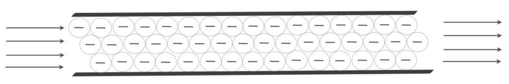
When you think about current through a wire, you can imagine electrons like marbles (or water), that are pushed through a pipe (see image above). Electrical current is measured in Amperes. If the current is one ampere (1A), it means that in one second 6,242*1018 electrons pass a given point. The more current flows through a wire, the thicker the wire should be. Check the video section of the webiste.
The amount of current (Ampere) through a wire is determined by the applied Voltage (V) to that wire and the amount of resistance (Ohm) of that wire. This brings us to Ohms law.
Ohms law
Some basics of electronics
To be able to understand a bit more about electronics and the circuits that are shown on this or other websites, it is actually inevitable to understand Ohm’s law – it makes live a bit easier. You have to understand what happens with the current, the voltage and the resistance. All these three variables are linked and make part of ‘Ohms Law’.
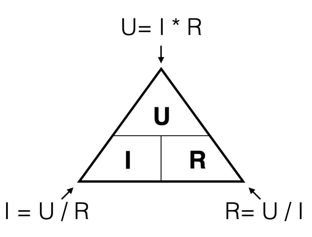
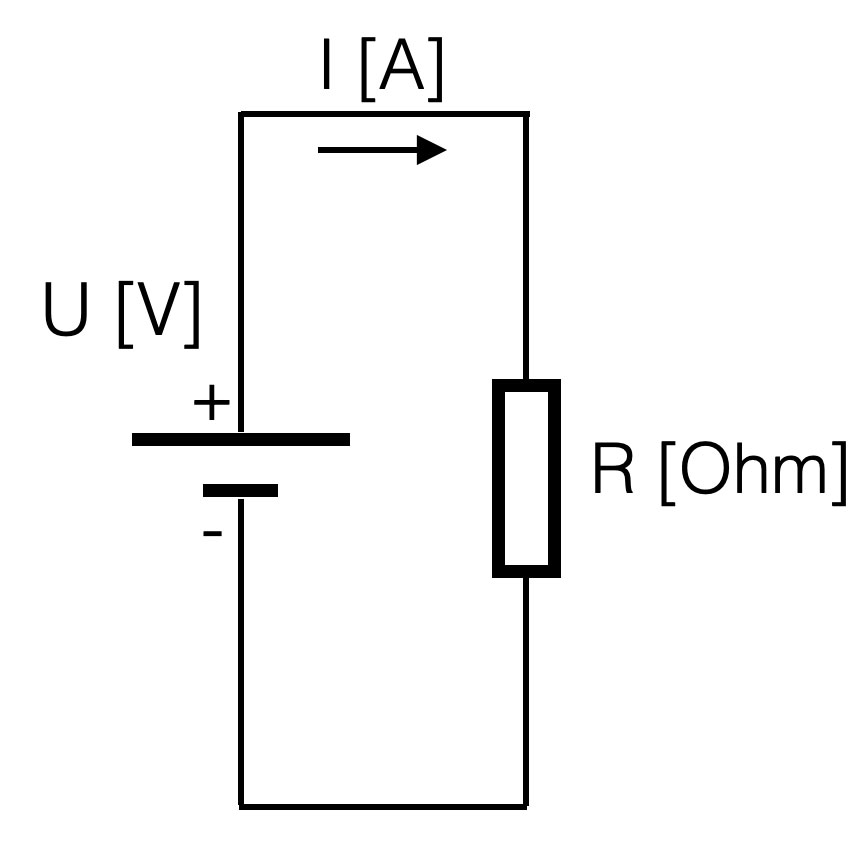
In formula: U = I x R
The voltage [V] is a product of the current {A]times the resistance [Ohm])
A graphical representation of this formula: when you look to the triangle from one of the three angles, you ‘see’ the formula’s for every variable. If you look from the top you ‘see’ U = I*R. Looking from the left corner beneath, you ‘see’ I=U/R.
In other words: the higher the value of the resistor, the lower the current given a constant voltage (the battery). If the resistance is 0 Ohm, we call this a short-circuit. A short circuit will result in a undefined value (too high) of the current (dividing by zero is not possible)
Suppose you have a battery of 9V. If you connect a resistor of 1kOhm (=1000 Ohm) parallel, the resulting current will be: I = (U / R) = 9 / 1000 = 9 mA = 0,009 Ampere (A) (9 mili Amp)
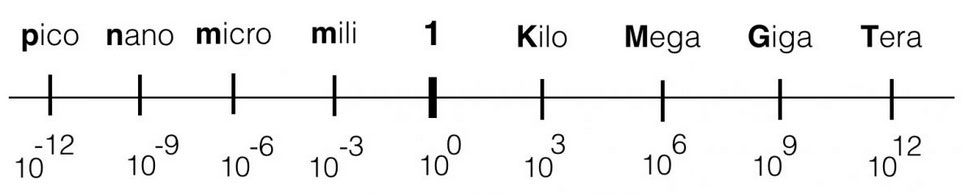
Within electronics, the values we use will vary from Tera (= 1000000000000) or 1012 ( a one with 12 zero’s) to pico: 0,000000000001. The engineering values always take steps of ‘3’ digits, in order to keep the notation clean and avoid errors.
Series
Voltage divider
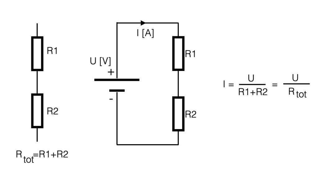
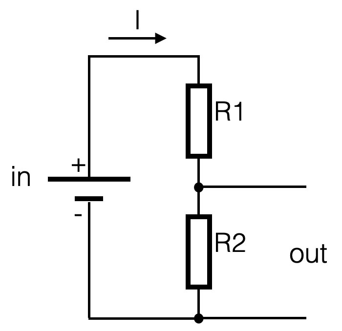
If resistors are placed in series (see figure below), the total resistance is a summation of al the resistors. So the total resistance in the example below is: R1+R2. If more resistors are placed in series, just add them up. If you have the total resistance, the current can be calculated in that circuit with ohm’s law.
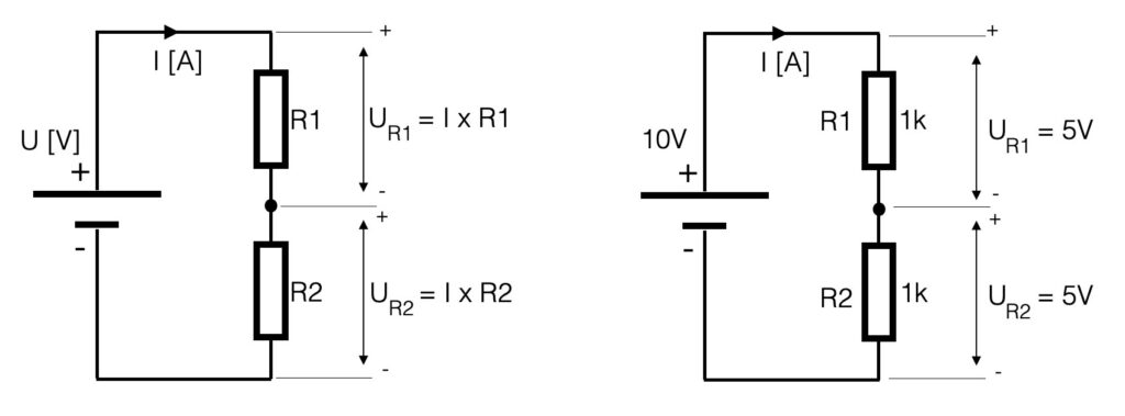
The current (I) in the series-circuit (see above) is the same in the whole circuit. There is only one branch. The voltage however is divided into equivalent parts. Another name for the circuit above is a voltage divider. The current through a resistor causes a ‘voltage-drop’ so with two resistors the voltage is divided into two values. If the series resistors have the same value (let’s say 1k), the value of the voltage parallel to the resistors is the same – the voltage is divided in equal parts. In case of the example below, the 10V of the power-supply is divided into two times 5V.
Be aware of the values that you use with these kind of calculations. Try to make use of the ‘engineering-values’ and avoid shifting comma’s. See the figure below.
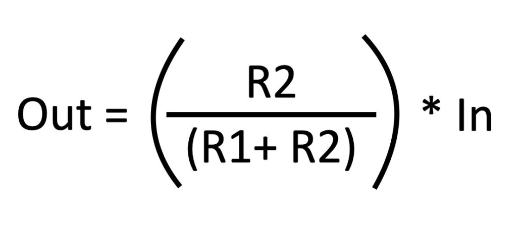
If we would look at the series circuit defining an input and an output, the battery is the input and the voltage parallel to R2 is defined to be the output. This is an important definition when we start to talk about filters!
The output of this series-circuit can be defined like this:
Parallel
Current divider
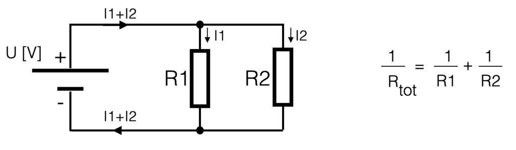
If resistors are placed parallel (see figure below), they divide the current in equivalent parts – hence the name current divider. The voltage parallel to the two resistors is for both resistors the same – it is one electrical node (= electrical point). The current however is divided into two separate current flows. The amount of current is determined by the value of the resistor. See the figure.
The total resistance of parallel resistors is the inverse of the series switched resistors. To calculate the total resistance you have to sum the inverses. This means that when resistors are connected parallel, the total resistance will go down. Suppose we have 2 resistors of 1kOhm placed parallel, the total resistance will be 500 Ohm.
Kirchoff
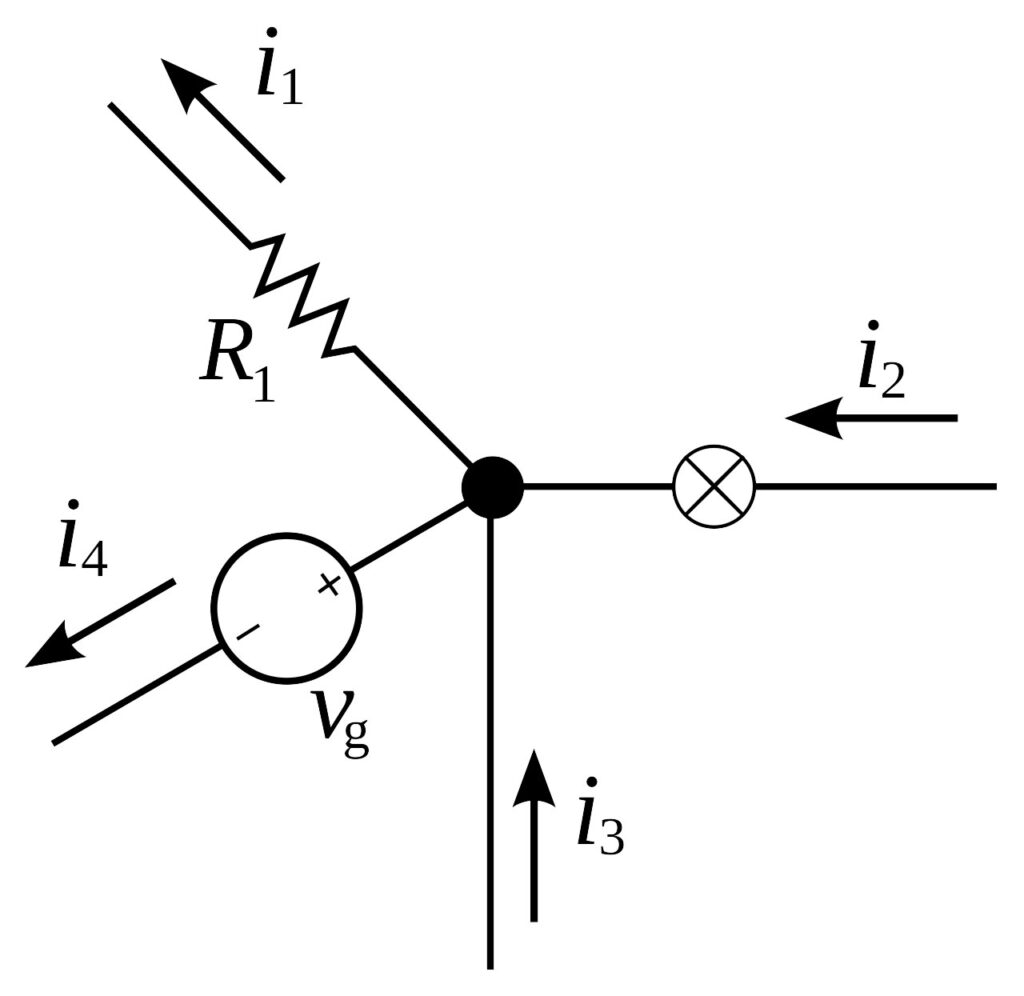
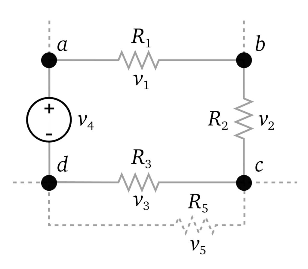
The behavior of current and voltage in a circuit is defined by the two laws of Kirchoff: Kirchoff’s first law:
For any node (junction) in an electrical circuit, the sum of currents flowing into that node is equal to the sum of currents flowing out of that node.
This means that the current entering any junction is equal to the current leaving that junction. In math: i2 + i3 = i1 + i4
Kirchoffs’s second law:
The directed sum of the potential differences (voltages) around any closed loop is zero.
The sum of all the voltages around a loop is equal to zero. In other words: v1 + v2 + v3 +v4 = 0
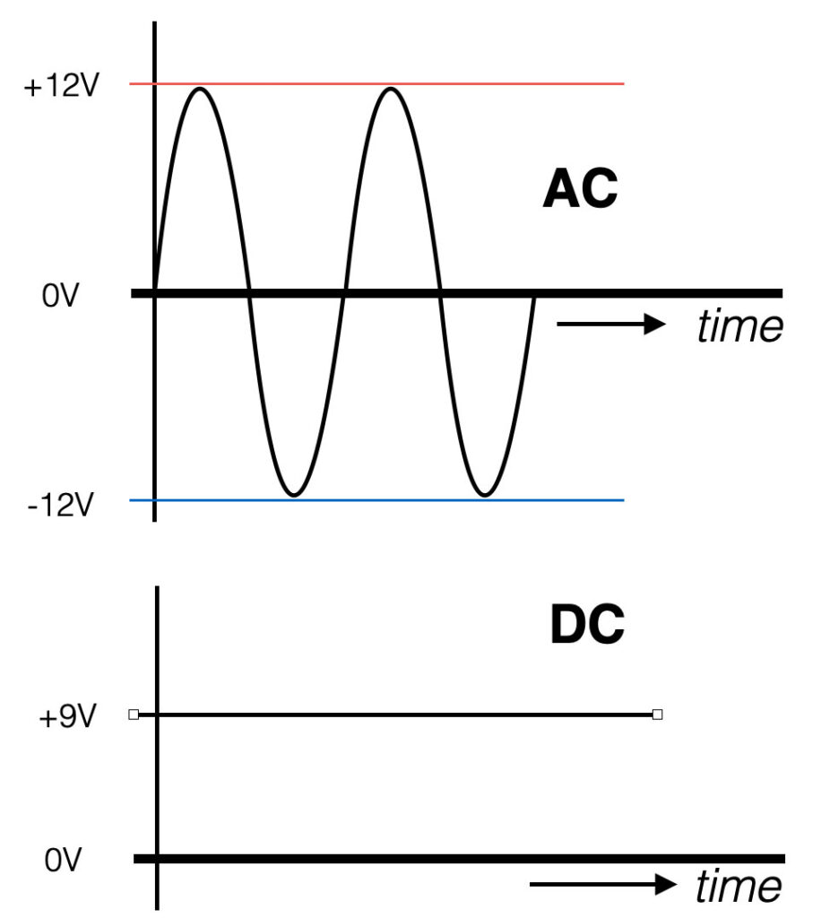
AC and DC
AC stands for Alternating Current. The value of the signal changes polarity over time with a certain frequency. The AC current will move both ways – back and forth.
DC stands for Direct Current. This means that the voltage does not change polarity over time. It is a straight line in the figure. Think about a battery. The plus (+) and minus (-) indicate you are dealing with DC. The current in the wire will move in one direction only.
Frequency
The frequency of a signal defines the amount of changes per second and is measured in units of Hertz [Hz]. So if we have an AC signal that changes (polarity) over time, this signal has a certain frequency.
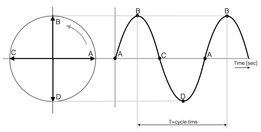
Looking at the figure below you see a representation of a sine-wave. The circle on the left represents a rotating point (think of the pedal of a bicycle) – with starting at point “A”. The point rotates left and will go up towards point “B”. If we would draw the position of the moving point in time, we will see the first 90 degrees of a sine-wave. Following the pedal from “C” to “D” and back to the beginning at point “A”, we see a full sine-wave (360 degrees). This one full circle is also called one cycle (T). The variable T indicates the cycle time in seconds.
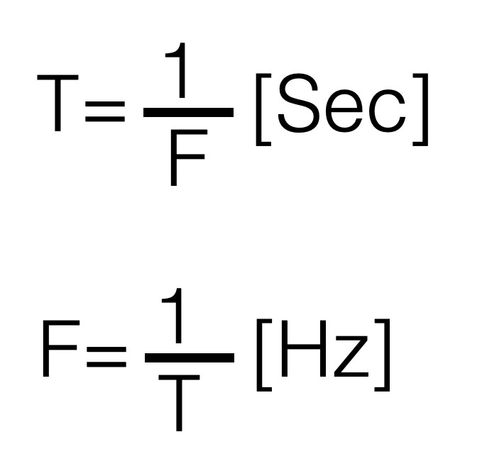
The amount of cycles that fit into one second (1 sec) is called the frequency F. So if we talk about a frequency of 1kHz (=1000Hz) this means that this signal makes 1000 cycles in one second.
Written in formula this looks like this. The smaller the cycle time , the higher the frequency.
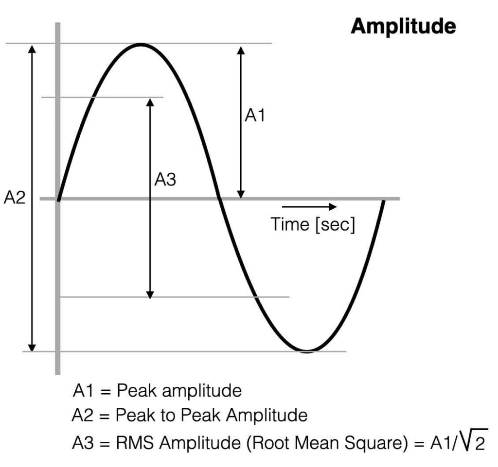
Amplitude
The Amplitude, often indicated with “A” is a value for the “strength” of a signal. The Peak to Peak Amplitude (A2 in the figure) is the change between the two ‘peaks’ of the sine-wave – the maximum swing.
If you want to measure the average value of the sine-wave, this is called the RMS value of the Amplitude. (A3) The multimeter shows the RMS-value.
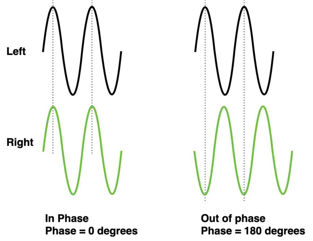
Phase
A mono signal cannot have ‘phase’, because phase is referring to a time difference between two repetitive signals. A sine-wave and a cosine-wave for example have a phase ‘angle’ of 90 degrees ( = 1/2π).
When two speakers are connected to an amplifier the correct way, both loudspeakers move forward and backward exactly the same time – the waves are ‘in phase’. If the connection of one speaker is then inverted (minus and plus swapped) we introduce two speakers that are ‘out of phase’. Check the waves below.
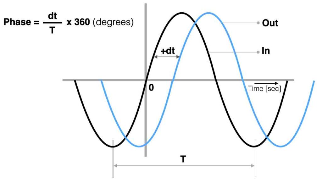
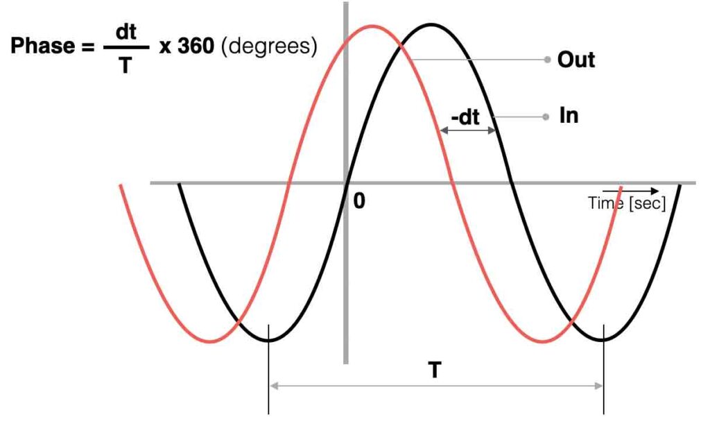
Electronic filters are created with time dependent components like capacitors or coils. When we connect an ac-signal (audio signal) to the input of a filter we can compare the in- and output to determine the ‘phase angle’ between both signals. In the figures below a positive- and negative phase example.